2-1
Note:
Follow the disassembly procedure in the numerical order given.
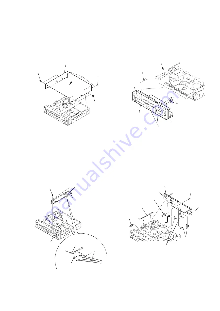
2-1. UPPER CASE REMOVAL
2-3. FRONT PANEL SECTION REMOVAL
2-2. REINFORCEMENT (C) BLOCK
REMOVAL
2-4. REAR PANEL BLOCK REMOVAL
SECTION 2
DISASSEMBLY
DVP-NC650V
1
Two tapping
screws
2
Two tapping
screws
3
Three tapping
screws
4
Upper case
1
Claw
3
Reinforcement
(C) block
Claw
AV-60 board
AV-60 board
Tweezers
— Bottom view —
Unhook the claw holding the tip
coming through the reverse side of
AV-60 board with tweezers.
2
Two screws
(B3)
2
Two screws (3 x 8)
6
Front panel
section
5
Claw
3
Claw
4
Two claws
1
Two connectors
(CN401, 404)
1
Connector (CN751)
1
Connector
(CN101)
2
Harness
5
Claw
4
Claw
6
8
Two connectors
(CN103, 105)
8
Connector (CN104)
7
Two flexible flat cables
(FAM-010: CN102/
FAM-009: CN201)
9
Rear panel block
3
Screw (B3)
Summary of Contents for DVP-NC650V
Page 1: ......


