5-54
2-4-3.
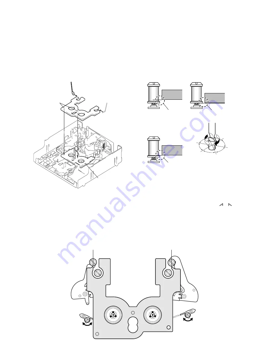
TG2/7 HEIGHT CHECK AND ADJUSTMENT
1. Preparation before check
1)
Check that the cassette compartment block has already been
removed. (Refer to page 5-35.)
2)
Set the mechanism deck to the loading end position (TG2 to 7
already moved to the loading end position and the pinch roller
is in the unloading position). Alternatively, set the mechanism
deck to the “LE position” using the mode selector II. (Refer to
page 5-35.)
3)
Place the TG2/7 preset plate (J-24).
2. Check and adjustment
Rotate the TG upper flange until the height of the TG2/7 preset
plate (J-24) and TG2 or TG7 roller block is the same. Alternatively,
rotate the TG upper flange of only TG2 by 60˚ in the direction of
raising the guide from the adjusted height while referring to the
figure below.
1. Preparation before check
1)
Check that the cassette compartment block has already been
removed. (Refer to page 5-35.)
2)
Set the mechanism deck to the loading end position (TG2 to 7
already moved to the loading end position and the pinch roller
is in the unloading position). Alternatively, set the mechanism
deck to the “LE position” using the mode selector II. (Refer to
page 5-35.)
3)
Place the TG2/7 preset plate (J-24).
2. Check and adjustment
Rotate each adjuster to adjust the TG2/7 position until
or
of
the TG2/7 preset plate (J-24), TG2 and TG7 are in line.
2-4-4.
FWD/RVS POSITION CHECK AND ADJUSTMENT
Face the mirror (J-14) in the
direction of the arrow and
perform a visual check.
Attach the boss while aligning it
with the hole of the cassette
reference plate (J-22).
TG2/7 preset plate
(J-24)
Boss
Cassette reference plate
(J-22)
Align the center of TG2 with the vertically
extended line of the jig plate's tip as shown.
TG2 arm
TG7 arm
Rotate the adjuster with a resin
screwdriver, etc. Be careful not
to bend the band.
Align the center of TG7 with the vertically
extended line of the jig plate's tip as shown.
TG2/7 preset plate (J-24)
Rotate the adjuster with a resin
screwdriver, etc. Be careful not
to bend the band.
TG2 or TG7
The guide is too low.
The guide is too high.
Screwdriver for tape path (J-15)
The guide
is raised.
The guide
is lowered.
Not good
Not good
Good
TG2 or TG7
TG2 or TG7
The normal height of TG2 is the position
where the TC upper flange is rotated by
60
°
in the direction of raising the guide
from the adjusted height while referring
to the figure below.
The normal height of TG7 is the current
one.
60
°
60
°
60
°
60
°
Summary of Contents for DSR-250
Page 11: ...1 1 SECTION 1 GENERAL DSR 250 250P This section is extracted from instruction manual DSR 250P ...
Page 12: ...1 2 ...
Page 13: ...1 3 ...
Page 14: ...1 4 ...
Page 15: ...1 5 ...
Page 16: ...1 6 ...
Page 17: ...1 7 ...
Page 18: ...1 8 ...
Page 19: ...1 9 ...
Page 20: ...1 10 ...
Page 21: ...1 11 ...
Page 22: ...1 12 ...
Page 23: ...1 13 ...
Page 24: ...1 14 ...
Page 25: ...1 15 ...
Page 26: ...1 16 ...
Page 27: ...1 17 ...
Page 28: ...1 18 ...
Page 29: ...1 19 ...
Page 30: ...1 20 ...
Page 31: ...1 21 ...
Page 32: ...1 22 ...
Page 33: ...1 23 ...
Page 34: ...1 24 ...
Page 35: ...1 25 ...
Page 36: ...1 26 ...
Page 37: ...1 27 ...
Page 38: ...1 28 ...
Page 39: ...1 29 ...
Page 40: ...1 30 ...
Page 41: ...1 31 ...
Page 42: ...1 32 ...
Page 43: ...1 33 ...
Page 44: ...1 34 ...
Page 45: ...1 35 ...
Page 46: ...1 36 ...
Page 47: ...1 37 ...
Page 48: ...1 38 ...
Page 49: ...1 39 ...
Page 50: ...1 40 ...
Page 51: ...1 41 ...
Page 52: ...1 42 ...
Page 53: ...1 43 ...
Page 54: ...1 44 ...
Page 55: ...1 45 ...
Page 56: ...1 46 ...
Page 57: ...1 47 ...
Page 59: ...1 49 ...
Page 60: ...1 50 ...
Page 61: ...1 51E ...
Page 284: ...ELECTRONIC VIEWFINDER DXF 801 DXF 801CE SERVICE MANUAL Attached Manual ...
Page 308: ...6 1 DXF 801 801CE MAIN MAIN COMPONENT SIDE Section 6 Board Layouts MAIN SOLDERING SIDE ...
Page 309: ...6 2 DXF 801 801CE SUB SUB COMPONENT SIDE SUB SOLDERING SIDE ...
Page 317: ...Sony EMCS Co DSR 250 250P 6 9 929 845 81 2001K1600 1 2001 11 Published by DI Customer Center ...
Page 321: ...DSR 250 250P Sony EMCS Co 9 929 845 82 2003A1600 1 2003 1 Published by DI Customer Center ...


