5-37
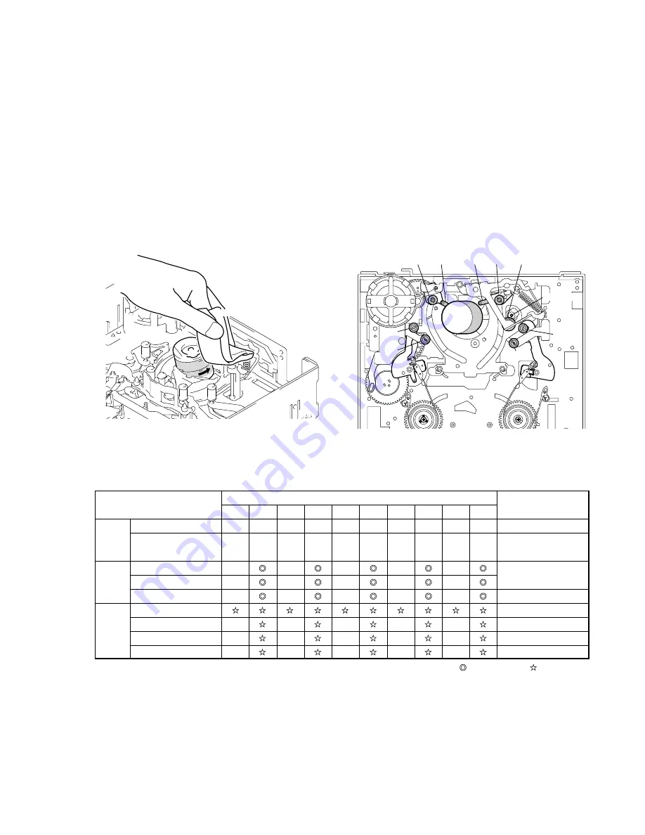
5-2-2. PERIODIC CHECK
• Carry out the following maintenance and periodic checks not only to fully display the functions and performance of the set, but also for the
equipment and tape. After replacing, service the set as follows, regardless of the length of use.
2-2-1.
CLEANING OF ROTARY DRUM ASSEMBLY
1.
Press a wiping cloth (J-12) moistened with cleaning fluid (J-
11) against the rotary drum assembly gently, and clean it while
rotating the rotary drum assembly slowly with your finger in
the counterclockwise direction.
Note:
Do not rotate the motor on power or rotate the rotary drum assembly
in the clockwise direction with your finger. The head tip will also be
damaged if the wiping cloth is moved perpendicularly against it.
Therefore, be sure to follow the above instructions when cleaning
the rotary drum assembly.
Note:
When overhauling, refer to the checks above and replace parts.
Note:
Greasing
Always use the specified grease. If the viscosity differs, various
problems may occur.
(Use SG-941 for all parts of the R mechanism.)
Check the quantity of grease when installing the parts which is
needed to apply the grease. When replacing these parts, make sure
to apply the specified amount of grease.
• FOIL (SG-941): Part No. 7-662-601-39
2-2-3.
PERIODIC CHECKS
2-2-2.
CLEANING OF TAPE PATH SYSTEM
1.
Clean the tape path systems (TG1 to TG8 and capstan) and the
lower drum using a super fine applicator (J-13) moistened with
cleaning fluid.
Note:
Make sure that no oil or grease of the link mechanisms sticks to the
super file applicator (J-13).
Note:
Do not use a applicator moistened with alcohol to the other guide
cleaning. But clean the pinch roller using alcohol.
Cleaning cloth
Rotary
drum assembly
TG 3
Pinch roller
Capstan
TG 8
TG 7
TG 6
TG 5
TG 4
TG 2
TG 1
Cleaning of tape path surface
Capstan (Bearing)
Cam motor (worm block)
Abnormal noise
Back tension measurement
Brake system
FWD/RVS torque measurement
Gear
–
Cleaning and degaussing
of rotary drum assembly
Make sure that no oil gets
on the tape path surface.
Be careful of the oil.
X-3946-702-1 (M902)
Be careful of the oil.
a
500
–
–
–
–
–
a
a
5000
a
–
a
4500
–
–
–
–
–
a
a
4000
a
–
a
3500
–
–
–
–
–
a
a
3000
a
–
a
2500
Hours of Use (H)
Location of Maintenance
and Check
Remarks
–
–
–
–
–
a
a
2000
a
–
a
1500
–
–
–
–
–
a
a
1000
a
Performance
Confirmation
Driving
System
a
: Cleaning : Appling grease : Confirmation
Summary of Contents for DSR-250
Page 11: ...1 1 SECTION 1 GENERAL DSR 250 250P This section is extracted from instruction manual DSR 250P ...
Page 12: ...1 2 ...
Page 13: ...1 3 ...
Page 14: ...1 4 ...
Page 15: ...1 5 ...
Page 16: ...1 6 ...
Page 17: ...1 7 ...
Page 18: ...1 8 ...
Page 19: ...1 9 ...
Page 20: ...1 10 ...
Page 21: ...1 11 ...
Page 22: ...1 12 ...
Page 23: ...1 13 ...
Page 24: ...1 14 ...
Page 25: ...1 15 ...
Page 26: ...1 16 ...
Page 27: ...1 17 ...
Page 28: ...1 18 ...
Page 29: ...1 19 ...
Page 30: ...1 20 ...
Page 31: ...1 21 ...
Page 32: ...1 22 ...
Page 33: ...1 23 ...
Page 34: ...1 24 ...
Page 35: ...1 25 ...
Page 36: ...1 26 ...
Page 37: ...1 27 ...
Page 38: ...1 28 ...
Page 39: ...1 29 ...
Page 40: ...1 30 ...
Page 41: ...1 31 ...
Page 42: ...1 32 ...
Page 43: ...1 33 ...
Page 44: ...1 34 ...
Page 45: ...1 35 ...
Page 46: ...1 36 ...
Page 47: ...1 37 ...
Page 48: ...1 38 ...
Page 49: ...1 39 ...
Page 50: ...1 40 ...
Page 51: ...1 41 ...
Page 52: ...1 42 ...
Page 53: ...1 43 ...
Page 54: ...1 44 ...
Page 55: ...1 45 ...
Page 56: ...1 46 ...
Page 57: ...1 47 ...
Page 59: ...1 49 ...
Page 60: ...1 50 ...
Page 61: ...1 51E ...
Page 284: ...ELECTRONIC VIEWFINDER DXF 801 DXF 801CE SERVICE MANUAL Attached Manual ...
Page 308: ...6 1 DXF 801 801CE MAIN MAIN COMPONENT SIDE Section 6 Board Layouts MAIN SOLDERING SIDE ...
Page 309: ...6 2 DXF 801 801CE SUB SUB COMPONENT SIDE SUB SOLDERING SIDE ...
Page 317: ...Sony EMCS Co DSR 250 250P 6 9 929 845 81 2001K1600 1 2001 11 Published by DI Customer Center ...
Page 321: ...DSR 250 250P Sony EMCS Co 9 929 845 82 2003A1600 1 2003 1 Published by DI Customer Center ...


