Preparations
2-5
Chapter 2 Preparations
2-2 Connection
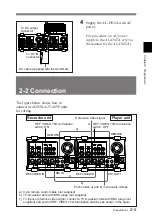
The figure below shows how to
connect two DNW-A25/A25P units
for editing.
To DC output
connector
To DC IN
connector
4
Supply the AC-DN2A with AC
power.
For procedure on AC power
supply to the AC-DN2A, refer to
the manual for the AC-DN2(A).
DC cable (supplied with the AC-DN2A)
Recorder unit
Player unit
a) 9-pin remote control cable (not supplied)
b) 75
Ω
coaxial cable with BNC plugs (not supplied)
c) To input a reference video signal, connect a 75
Ω
coaxial cable with BNC plugs (not
supplied) and set the REF. VIDEO 75
Ω
termination switches as shown in the figure.
REF. VIDEO IN
REF. VIDEO IN
REMOTE
REMOTE
SDI OUT 1
SDI IN
REF. VIDEO 75
Ω
termination
switch: ON
REF. VIDEO 75
Ω
termination
switch: OFF
a)
c)
c)
b)
Push cables a) and b) in the cable clamps.
Reference video signal
Summary of Contents for DNW-A25
Page 1: ...DIGITAL VIDEOCASSETTE RECORDER DNW A25 A25P OPERATION MANUAL 1st Edition Revised 4 English ...
Page 100: ......
Page 136: ......
Page 162: ......


