93
Basic Switcher Settings
Chapt
er
3
Pre
par
at
ion
s
1
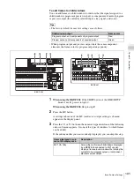
When using the BKDF-901:
Press the AUX button.
When using the BKDF-902:
From among the buttons AUX03 to AUX10,
press one to which analog output has been assigned.
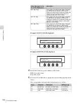
The Aux (AUX output assignment settings) sub menu appears in the display
panel.
2
Press the
h
or
H
button in the numeric keypad until the Output (output
detailed settings) sub menu appears.
“Output” appears in the sub menu title display area. If it is already displayed
there, you can skip this step.
3
When using the BKDF-901:
Rotate the F1 knob to select an item from
among AUX03 to AUX10 to which analog output has been assigned.
When using the BKDF-902:
Skip to step
4
.
4
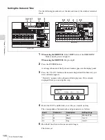
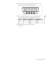
Rotate the F2 knob to select the output signal type.
Compst:
Analog composite signal
Y/CB/CR:
Analog component (color difference) signal
GBR/wSync:
Analog component (RGB) signal (sync signal multiplexed
into G signal)
• Analog HD component signals cannot be output.
• The following table lists the signals to be connected and the number
assigned to each input channel
.
BKDF-901
BKDF-902
Notes
Summary of Contents for DFS-900M
Page 189: ...189 Pattern List Appendix Pattern List Wipe Basic wipe ...
Page 190: ...190 Pattern List Appendix User wipe ...
Page 191: ...191 Pattern List Appendix Mask ...
Page 193: ...193 Pattern List Appendix ...
Page 194: ...194 Pattern List Appendix 3D DME effects ...
Page 195: ...195 Pattern List Appendix ...
Page 196: ...196 Pattern List Appendix User effects ...
Page 216: ...216 External Dimensions Appendix BKDF 902 1 5M E Control Panel Unit mm inches ...
Page 217: ...217 External Dimensions Appendix DFS 900M Processor Unit Unit mm inches ...


