


198
Messages and Actions to Take
A
ppen
dix
Config Error (abbcc)
Appears if an internal FPGA
(Field-Programmable Gate Array)
fails to start when the processor
starts.
abbcc: Five-digit hexadecimal
error code
a=1: CPU_FPGA error
a=2: COMB_FPGA error
a=3: I/O expansion board error,
standard I/O board error or
function expansion board
error
When a=1 or a=2, bb and cc are 0.
When a = 3, the values of bb (bit0
to bit5) and of cc (bit0 to bit7) show
where the error occurred.
bit: 1 for the FPGA which failed
in activation, and 0 for the
FPGA which is normally
activated.
The relation between bits and error
locations are as follows.
bit0: Left board on lower
installation tray
bit1: Center board on lower
installation tray
bit2: Left board on upper
installation tray
bit3: Center board on upper
installation tray
bit4: Right board on lower
installation tray
bit5: Right board on upper
installation tray
cc: Standard I/O board/function
expansion board error
bit0: Standard I/O board
(MAIN_IO)
bit1: Standard I/O board (XPT)
bit2: Standard I/O board
(KEYER)
bit3: Standard I/O board (DME)
bit4: Function expansion board
in DME1 socket
bit5: Function expansion board
in DME2 socket
bit6: Function expansion board
in MV1 socket
bit7: Function expansion board
in MV2 socket
Power the processor off and then
power it on again. If the error
persists, reprogram the FPGA. If
the error still persists, the board
may need to be replaced.
Note
FPGAs start in the following order
(
3
and
4
at the same time).
1
CPU_FPGA
2
COMB_FPGA
3
I/O expansion board FPGAs
4
Standard I/O board and
function expansion board FPGAs
If an error occurs at
1
, the error is
detected only for
1
because
2
to
4
are not activated. In the same
way, if an error occurs at
2
, the
error is detected only for
2
because
3
and
4
are not
activated.
Therefore, another error may occur
when the system starts again,
even after correcting a detected
error.
DME assign failure
Appears when the DME option
installation status has changed
after shutting down the switcher,
and the previous number of DME
channels cannot be restored after
the switcher starts.
Check the current DME option
installation status.
DME assign too much
DME assign too much.
Reduce!
Appears when an attempt is made
to use a new DME channel, even
though the maximum number of
DME channels are already in use.
Reduce the number of DME
channels and try the operation
again.
DME No. reserved
Appears when no DME effect is
registered for the selected number.
Select another DME effect.
Message
Description
Action to take
Display panel
GUI menu screen
Summary of Contents for DFS-900M
Page 189: ...189 Pattern List Appendix Pattern List Wipe Basic wipe ...
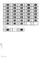
Page 190: ...190 Pattern List Appendix User wipe ...
Page 191: ...191 Pattern List Appendix Mask ...
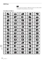
Page 193: ...193 Pattern List Appendix ...
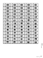
Page 194: ...194 Pattern List Appendix 3D DME effects ...
Page 195: ...195 Pattern List Appendix ...
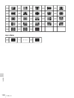
Page 196: ...196 Pattern List Appendix User effects ...
Page 216: ...216 External Dimensions Appendix BKDF 902 1 5M E Control Panel Unit mm inches ...
Page 217: ...217 External Dimensions Appendix DFS 900M Processor Unit Unit mm inches ...


