


5-12
Address
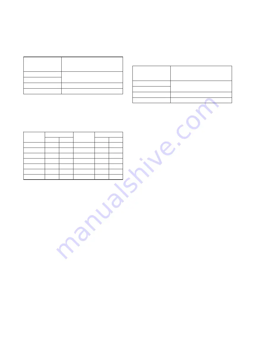
24
25
26
27
28
29
36
PAL
2C
17
78
1D
FB
12
D6
Address
37
38
39
3A
3B
3C
3D
PAL
E6
23
00
19
00
27
A8
4. Flange Back Adjustment
The inner focus lens flange back adjustment is carried out
automatically. In whichever case, the focus will be deviated during
auto focusing/manual focusing.
4-1. Flange Back Adjustment(1)
Subject
Flange back adjustment chart
(2.0 m from the front of the lens)
(Luminance: 230 ± 30 lux)
Measurement Point
Check operation on TV monitor
Measuring Instrument
Adjustment Page
F
Adjustment Address
24 to 29, 36 to 3D
Adjusting method:
1)
Check that at both the zoom lens TELE end and WIDE end,
the center of the chart for the flange back adjustment and center
of the exposure screen coincide.
2)
Select page: 0, address: 01, and set data: 01.
3)
Check that the data of page: F, address: 24 to 29, 36 to 3D is
the initial value (See table below).
4)
Select page: 6, address: 02, and check that the data is “00”.
5)
Select page: 6, address: 01, set data: 13, and press the PAUSE
button of the adjustment remote commander.
6)
Select page: 6, address: 01, set data: 15, and press the PAUSE
button of the adjustment remote commander.
( The adjustment data will be automatically input to page: F,
addresses: 24 to 29, 36 to 3D.)
7)
Select page: 6, address: 02, and check that the data is “01”.
Processing after Completing Adjustments
1)
Select page: 6, address: 01, set data: 00, and press the PAUSE
button of the adjustment remote commander.
2)
Perform “Flange Adjustment (2)”.
NTSC
8E
1A
80
24
65
11
D6
NTSC
E6
15
45
3F
3F
16
A8
Data
Data
4-2. Flange Back Adjustment (2)
Perform this adjustment after performing “Flange Back Adjustment
(1)”.
Subject
Subject more than 500m away
(Subjects with clear contrast such as
buildings, etc.)
Measurement Point
Check operation on TV monitor
Measuring Instrument
Adjustment Page
F
Adjustment Address
24 to 29, 36 to 3D
Adjusting method:
1)
Set the zoom lens to the TELE end and expose a subject that is
more than 500 m away (subject with clear contrast such as
building, etc.). (Nearby subjects less than 500 m away should
not be in the screen.)
2)
Select page: 0, address: 01, and set data: 01.
3)
Select page: 6, address: 02, and check that the data is “00”.
4)
Select page: 6, address: 01, set data: 13, and press the PAUSE
button of the adjustment remote commander.
5)
Place a ND filter on the lens so that the optimum image is
obtain.
6)
Select page: 6, address: 01, set data: 29, and press the PAUSE
button of the adjustment remote commander.
(The adjustment data will be automatically input to page: F,
addresses: 24 to 29, 36 to 3D.)
7)
Select page: 6, address: 02, and check that the data is “01”.
Processing after Completing Adjustments
1)
Select page: 0, address: 01, and set data: 00.
2)
Select page: 6, address: 01, set data: 00, and press the PAUSE
button of the adjustment remote commander.
3)
Perform “Flange Back Check”.
Summary of Contents for DCRTRV900 - MiniDV Handycam Digital Video Camcorder
Page 10: ...1 2 ...
Page 11: ...1 3 ...
Page 12: ...1 4 ...
Page 13: ...1 5 ...
Page 14: ...1 6 ...
Page 15: ...1 7 ...
Page 16: ...1 8 ...
Page 17: ...1 9 ...
Page 18: ...1 10 ...
Page 19: ...1 11 ...
Page 20: ...1 12 ...
Page 21: ...1 13 ...
Page 22: ...1 14 ...
Page 23: ...1 15 ...
Page 24: ...1 16 ...
Page 25: ...1 17 ...
Page 26: ...1 18 ...
Page 27: ...1 19 ...
Page 28: ...1 20 ...
Page 29: ...1 21 ...
Page 30: ...1 22 ...
Page 31: ...1 23 ...
Page 32: ...1 24 ...
Page 33: ...1 25 ...
Page 34: ...1 26 ...
Page 35: ...1 27 ...
Page 36: ...1 28 ...
Page 37: ...1 29 ...
Page 38: ...1 30 ...
Page 39: ...1 31 ...
Page 40: ...1 32 ...
Page 41: ...1 33 ...
Page 42: ...1 34 ...
Page 43: ...1 35 ...
Page 44: ...1 36 ...
Page 45: ...1 37 ...
Page 46: ...1 38 ...
Page 47: ...1 39 ...
Page 48: ...1 40 ...
Page 49: ...1 41 ...
Page 50: ...1 42 ...
Page 51: ...1 43 ...
Page 52: ...1 44 ...
Page 53: ...1 45 ...
Page 54: ...1 46E ...
Page 64: ...DCR TRV890E TRV900 TRV900E SECTION 3 BLOCK DIAGRAMS 3 1 OVERALL BLOCK DIAGRAM 3 1 3 2 3 3 3 4 ...
Page 65: ...DCR TRV890E TRV900 TRV900E 3 2 POWER BLOCK DIAGRAM 3 5 3 6 3 7 3 8E ...