


6-9
7C
3F
CF or CC
4D
4F
43
04
39
0E
75
44
00
27
29
36
02
0C
EC
2C
37
F2
76
C0
1C
02
65
AC
0A
D8
28
2A
76
73
76
65
77
77
A4
2D
0D
04
14
10
7C
3F
CF
4D
4F
43
00
39
1C
75
46
00
27
29
36
02
0C
F0
2C
37
F2
76
C0
1C
02
65
AC
0A
D8
28
2A
76
73
76
65
77
77
A4
2D
10
04
14
10
1-2.
CAMERA SYSTEM ADJUSTMENTS
Note:
Check that the following adjustment has been completed
before performing “Camera Check Adjustments”.
1. “Initializing the Page D Data” and “Changing the Page D
Data” of “System Control System Adjustments” of “Video
Section Adjustments”.
2. “Base Band Block Adjustment” and “Clock Adjustment”
of “Video System Adjustments” of “Video Section
Adjustments”.
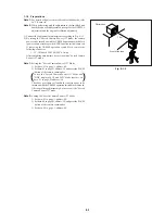
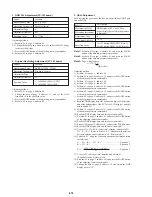
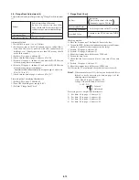
1. Initializing the Page F Data
Note:
If the page F data is initialized, all adjustments in “Camera
System Adjustments” must be performed again.
Initializing Method:
1) Set data: 01 to page: 6, address: 00.
2) Set data: 2D (NTSC) or data: 2F (PAL) to page: 6, address: 01,
and press the PAUSE button of the adjusting remote commander.
3) Set data: 01 to page: 6, address: 03, and press the PAUSE button
of the adjusting remote commander.
4) Check that the data of page: 6, address: 02 is 01.
5) Set data: 00 to page: 6, address: 00.
6) Turn OFF the main power (8.4V).
7) Perform “Changing the Page F Data”.
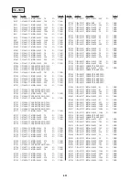
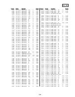
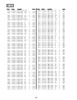
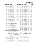
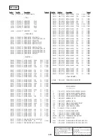
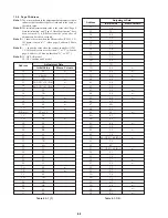
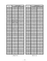
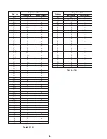
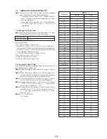
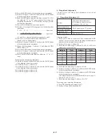
2. Changing the Page F Data
If the page F data has been initialized, change the data as shown in
the following table by manual input.
Note 1:
Before changing the data, set data: 01 to page: 6, address:
00.
Note 2:
When changing the data, press the PAUSE button of the
adjusting remote commander each time when setting new
data to write the data in the non-volatile memory.
Note 3:
After changing the data, set data: 00 to page: 6, address:
00. Also perform the next camera system adjustment.
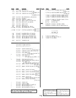
Note 4:
Change the data for address: 79 only when the HI controller
(IC2501, VC-183 board) version is “1” (only when the
data of page: 2, address: FF is “01” ).
Note 5:
Change the data for address: A4 only when the camera
controller (IC205, VC-183 board) version is other than “1”
or “2” (only when the data of page: 6, address: FF is other
than “01” or “02” ).
Note 6:
CC: AEP, UK model
CF: E model
18
1A
1B (Note 6)
47
49
4A
50
51
53
5B
75
79 (Note 4)
85
86
89
8B
8C
90
91
92
A4 (Note 5)
A5
A6
A9
B6
C1
CB
CC
CD
CE
CF
D1
D2
D3
D4
D5
D6
D7
EA
EB
EC
ED
EE
Address
DATA
PAL
NTSC
Adjusting Page
Adjusting Address
F
00 to FF
Summary of Contents for DCR-PC7
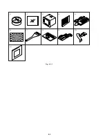
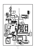
Page 41: ...6 2 Fig 6 1 1 J 1 J 2 J 3 J 4 J 5 J 6 J 7 J 8 J 9 J 10 J 11 ...
Page 92: ...6 57 ...
Page 95: ...6 60 ...
Page 96: ...6 61 ...
Page 97: ...6 62 ...
Page 104: ... 282 Sony EMCS Co DCR PC7 PC7E 9 973 919 11 2006I0500 1 2006 9 Published by Kohda TEC ...


