5-21
M
G
Y
E
C
Y
R-Y
B-Y
R
B
G
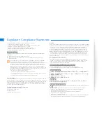
Burst position
M
G
Y
E
C
Y
R-Y
B-Y
R
B
G
Burst position
For NTSC mode
For PAL mode
Fig. 5-1-16
Fig. 5-1-17
11. Color Reproduction Check
Mode
STILL
Subject
Color bar chart
(Color reproduction adjustment frame)
Measurement Point
Video terminal of A/V OUT jack
(75
Ω
terminated)
Measuring Instrument Vectorscope
Specified Value
All color luminance points shouldsettle
within each color reproduction frame.
Menu setting:
1)
VIDEO OUT of SET UP menu
................................
NTSC (NTSC mode)
................................
PAL (PAL mode)
Checking method:
1)
Select page: 0, address: 01, and set data: 01.
2)
Select page: 5, address: F1, and set data: FF.
3)
Select page: D, address: 63, set data: 40, and press the PAUSE
button of the adjusting remote commander.
4)
Perform “ Data setting during camera system adjustment”.
(Refer to page 5-13)
5)
Check that the picture frame is set to the specified position.
(Refer to “6. picture Frame Setting” )
6)
Select page: 6, address: 10, and set data: 01.
7)
Select page: E, address: 52, after noting down the data, set
data: 0A, and press the PAUSE button.
8)
Select page: 6, address: 01, set data: 0F, and press the PAUSE
button.
9)
Select page: 6, address: 12, set data: 80, and press the PAUSE
button.
10) Wait for 1 second.
11) Select page: 6, address: 12, set data: 00, and press the PAUSE
button.
12) Wait for 2 seconds.
13) Check the each color luminance point in each color repro-
duction frame.
Processing after Completing Adjustments:
1)
Select page: 6, address: 01, set data: 00, and press the PAUSE
button of the adjusting remote commander.
2)
Select page: 6, address: 10, and set data: 00.
3)
Select page: E, address: 52, set data noted down at step 8)
and press the PAUSE button.
4)
Select page: 5, address: F1, and set data: 00.
5)
Select page: D, address: 63, set data: 00, and press the PAUSE
button.
6)
Release the data setting performed at step 4).
(Refer to page 5-13)
7)
Select page: 0, address: 01, and set data: 00.