5-5
Fig. 5-1-5
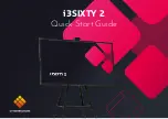
Note 1: In changing data, wait for more than 5 seconds after the
set was turned on, then change the data.
Note 2: Must be connected when performing the battery
down adjustment.
Note 3: Don’t use the 12 pin flexible board of CPC-9 jig.
It causes damage to the unit.
Note 4: The old CPC-9 jig (Parts code: J-6082-393-B)
cannot be used, because it cannot operate the
adjustment remote commander.
Adjustment remote
commander
CPC-9 jig
(J-6082-393-C)
Flash unit
DC-IN
Connector
AC power
adaptor
AC IN
Memory
Stick
MS-54 board
CN001
CN005
CN003
CN001
CN711
SY-58
board
LCD holder block
CN704
CN851
CN706
CN701
CN705
CN708
CN707
DD-141
board
CN183
CN702
CN101
CN709
CN302
CN151
J251
CN251
CN851
CN901
CN802
CN801
CN301
Control switch
block (Mode SW)
DC power supply
(6.0 to 7.2 V DC)
(Note 2)
Control switch
block
(Zoom/power SW)
PD-128
board
Inverter
transformer
unit
AV
OUT
Video
(Yellow)
Audio
(White)
Terminated
at 75
Ω
Vector
scope
Color monitor
Extension Cable
(J-6082-398-A): L=200mm
(J-6082-357-A): L=100mm
CN703
SL-56
board
Lens
block
assembly
CD-282
board
Extension Cable
(J-6082-423-A)
12 pin
18 pin
12
1
18
1
–
+
1
18