


35
CDX-5V661/5V661A/5V661D/5V661S
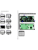
LED PWM Adjustment without Jig
Setting:
• Open the KEY board on the set to be adjusted and disconnect the bias resistor for the LED to be adjusted, then connect a variable
resistor.
Combined resistance
Indicator LED: 1.5 k
Ω
or more
Dimmer LED: 800
Ω
or more
(Example) In the case of Indicator LED (D11): Disconnect R31 to R33.
• Darken the room.
Note on replacing LED:
•
When luminance of replaced LED is different from other LEDs, (in case it is darker as well as brighter) replace all LEDs in the group.
Group means D11 - D16 of Indicator LED, D3 - D10 of dimmer LED.
•
Select resistance value taking 10 mA max and electrical power of adjusted resistance value in consideration.
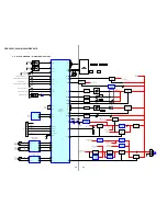
PWM signal
Duty 100%
20%
Indicator LED
(R31 to R48)
Dimmer LED
(R55 to R62, R65 to R76)
Microcomputer
Adjusted parts (see page 36)
(Power supply)
(DC13.0V)
Duty GEN.
+
–
+
–
(Power supply)
(DC13.0V)
Duty GEN.
+
–
+
–
Adjusted set (replaced or repaired set)
Standard set (normal set)


