


17
CDX-5V661/5V661A/5V661D/5V661S
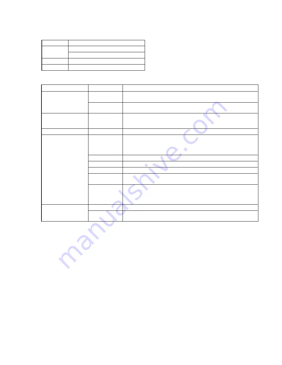
Jig Connection/Connectors
Destination
Name
CDC
UART connector (for design)
PANA-BUS connector
PC
RS-232C connector (for design)
H/U
PANA-BUS connector (for design)
Use of Each Switch and LED on the Jig
Name
Type
Use
SCAN
Blink
t
Disc scan
MODE LED
Lit
t
All scan
(Number to be adjusted)
SHUFFLE
Blink
t
Disc shuffle
Lit
t
All shuffle
DTMS
Display
7 seg LED
×
8
Aging count
Error
Rotary SW
12 steps
Operation mode selection
UART line selection
LINE
CDC: PC
y
CDC
JIG: PC
y
JIG
FL-CDC
Set CDC microcomputer to the Flash Rewrite mode.
Toggle SW
FL-JIG
Set Jig microcomputer to the Flash Rewrite mode.
CONTROL
Control voltage
RS-232C
To use straight cable: STRAIGHT
CABLE SELECT
To use cross cable: CROSS
Head Unit selection
H/U
RADIO: Radio connection mode
JIG: PANA-BUS standalone mode
Push SW
1 to16
Execution keys according to each operation mode
RST
Reset key for Jig and CDC microcomputers
However, CDC cannot be reset unless the UART connector is connected.


