7
16
GB
Other Functions
Setting the Pla
y
er to
T
urn Off
A
utomaticall
y
(P
o
wer Sa
ve
Function)
Z
When the Po
wer Sa
v
e function is on, the player will
automatically turn of
f (change to ST
ANDBY) after
se
v
eral minutes of inacti
vity
.
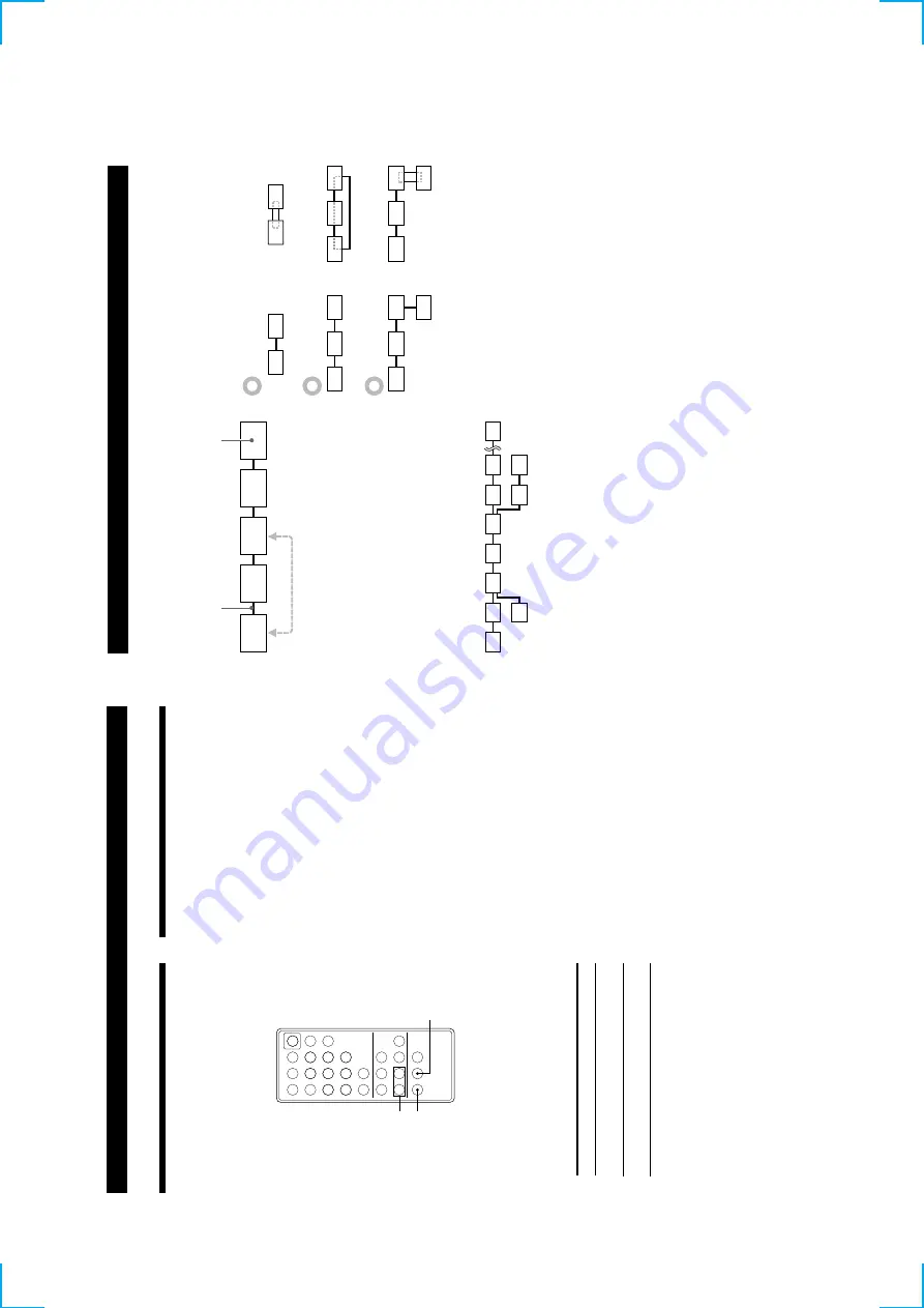
YES
MENU/NO
./>
?/1
.>
m
M
NX
x
789
>10
10
/0
123
456
1
Before playing a disc, press MENU/NO repeatedly
until
“Setup Menu
” appears in the display
.
2
Press
./
>
until
“Po
wer Sa
v
e”
appears, then
press YES.
3
Press
./
>
to select the setting, then press
YES.
T
o
Select
T
urn on the Po
wer Sa
v
e
function
Po
wer Sa
v
e On
(def
ault setting)
T
urn of
f
the
Po
wer
Sa
v
e
function
Po
wer Sa
v
e
Of
f
4
Press MENU/NO.
About
i.LINK
This section e
xplains the general specif
ications and
major features of i.LINK. Read this section before
doing an
y i.LINK-related operation.
Note that i.LINK connections and operations may v
ary
,
depending on the component. F
or details re
garding
the connection of i.LINK components to this player
, see
“Hooking Up the System
” on page 4.
i.LINK functions
i.LINK is a serial digital interf
ace that supports the bi-
directional transmission of audio and video signals,
commands, and e
v
en component status information.
All that is needed to hook up i.LINK components are
i.LINK connecting cables.
Audio and video
components connected within an i.LINK conf
iguration
can be used to perform a wide range of operations and
data e
xchanges that is sure to e
xpand as the number
and v
ariety
of
i.LINK
components
gro
w
.
Since i.LINK allo
ws data to be transmitted from one
component to other components to which it is not
directly connected, there is no need to pay attention to
connection order
. Ho
we
v
er
, due to dif
ferences in
characteristics or specif
ications, operation of or data
exchange with certain i.LINK components may not be
possible, e
v
en when the
y are connected.
z
What is i.LINK?
i.LINK is a trademark proposed by Son
y Corporation
and accepted by companies throughout the w
orld as an
easy-to-remember name for the IEEE 1394 w
orld
standard of the Institute of Electrical and Electronics
Engineers.
17
GB
Other Functions
i.LINK connections
The use of i.LINK cables to connect i.LINK components
as sho
wn belo
w
is called a
“daisy chain
” conf
iguration.
Data can be transmitted between an
y tw
o
components e
ven if the
y
are indirectl
y
connected.
Branc
h
connections
•
An
y i.LINK component with three or more i.LINK
connectors can serv
e as a branch point.
•
Up to 63 i.LINK components can be connected in a
single conf
iguration. Ho
we
v
er
, the maximum
number of components that can be daisy-chained in
a single route is 17 (i.e., a maximum of 16 i.LINK
connecting cables in a ro
w). Each i.LINK cable used
in a single route is called a
“hop.
” F
o
r e
xample,
there are 6 hops in the route between
A and C in the
illustration belo
w
, and 3 hops in the route between
A
and D.
B
A
DC
Each route between
A and B;
A and C;
A and D; B and
C; B and D; and C and D in the illustration abo
v
e can
ha
v
e 16 hops (i.e., 17 components).
Loop-connetion
A signal output from one component is transmitted to
all other components.
A loop connection should thus
be a
v
o
ided to pre
v
ent the return of a signal to its
source.
Notes
•
Some i.LINK components (such as personal computers) do
not transfer signals when the
y
are turned of
f. Refer to the
operation manual of each component to be connected
before you
hook them
up.
•
The maximum transmission rate of an i.LINK component is
printed near its i.LINK connector
.
The indications S100,
S200, and S400 refer to maximum transmission rates of 100,
200, or 400 Mbps*, respecti
v
ely
.
The actual transmission
rate may be f
aster or slo
wer
, depending on the dif
ferences
in transmission rates and specif
ications among the
connected components.
z
What is Mbps?
“Mbps
” is an abbre
viation for me
gabits per second. It
indicates the amount of data transmitted per second. F
o
r
example, a rate of 200 Mbps means 200 me
gabits of data
are transmitted
in
one
second.
(Contin
ued)
i.LINK connecting cab
le
i.LINK component
Correct
Incorrect (looped)
Summary of Contents for CDP-LSA1
Page 22: ...22 Adjustment Location BD BOARD SIDE B TP FE TP TE TP VC TP XPCK TP RFAC IC103 30 16 15 1 ...
Page 30: ...CDP LSA1 30 30 6 7 SCHEMATIC DIAGRAM MAIN 1 3 SECTION See page 28 for Printed Wiring Board ...
Page 35: ...CDP LSA1 35 35 6 11 SCHEMATIC DIAGRAM PANEL SECTION See page 33 for Waveforms ...
Page 37: ...CDP LSA1 37 37 6 13 SCHEMATIC DIAGRAM POWER SECTION ...


