background image

10

Preparation and Setting

Preparation and 
Setting

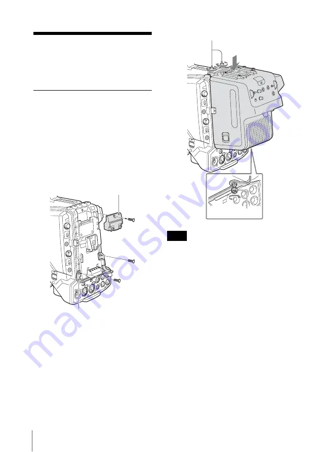
Attaching the Adaptor to a 
Camera/Camcorder

1

Loosen the screws on the 50P 
cover of the camera or camcorder, 
then remove it.

2

Fix the supplied CA bracket on the 
battery attachment shoe of the 
camera or camcorder using the two 
screws (+K2.6×5).

3

Slide down the adaptor from the 
upper side of the battery 
attachment shoe of the camera/
camcorder.

4

Tighten the attachment screws at 
the top (2) and lower part (1) of the 
adaptor.

Tighten the screws securely so that the 
unit will not fall off.

To remove

Perform the installation procedure in 
reverse, loosening the screws that were 
tightened then.

50P cover

CA bracket

Note

Attachment screws

Attachment screws

Summary of Contents for CA-TX70

Page 1: ...4 452 968 01 1 2012 Sony Corporation HD Camera Adaptor Operating Instructions Before operating the unit please read this manual thoroughly and retain it for future reference CA TX70 ...

Page 2: ...ursuant to Subpart B of Part 15 of FCC Rules This device complies with Part 15 of the FCC Rules Operation is subject to the following two conditions 1 this device may not cause harmful interference and 2 this device must accept any interference received including interference that may cause undesired operation For the customers in Canada This Class A digital apparatus complies with Canadian ICES 0...

Page 3: ... to a Camera Camcorder 10 Connecting a Camera Control Unit CCU 11 Attaching the Accessory Shoe Kit 12 Outputting Trunk Signal 13 Using an Intercom 13 Starting the System 14 Setting the System Format 14 Error Messages 16 Important Notes on Operation 17 Specifications 19 General 19 Connectors 19 Supplied Accessories 19 Other peripheral devices 19 Pin assignment 20 ...

Page 4: ...nection of input and output signals or power supplies via the 50 pin interface and BATT interface As no cables are necessary for attachment the adaptor offers a solution for solid camera system configuration Digital triax transmission The CCU and camera are connected using the industry standard double shielded triaxial camera cable commonly referred to as triax The latest Sony developed digital tr...

Page 5: ...een qs PGM volume control qa MIC switch 7 INTERCOM volume control 9 POWER switch 6 CALL button qd Screw holes for V wedge shoe attachment of HD viewfinder 3 TALLY switch 5 RET 1 button 4 RET button RET 2 3 4 switch qj RETCTRL connector qg INTERCOM connector qh PROMPTER connector 0 POWER lamp red green 8 INTERCOM line switch Front ...

Page 6: ...it is monitored on the viewfinder screen while this button is pressed If you press both the RET 1 button and RET button RET 2 3 4 the RET 1 button takes priority When the adaptor is connected to the PMW 500 350 320 Solid State Memory Camcorder if you change the return video signal the previously selected return signal may be displayed for a moment in the viewfinder When the adaptor is connected to...

Page 7: ...level of program 1 m Screw holes for V wedge shoe attachment of HD viewfinder These are V wedge shoe attachment for HD viewfinder screw holes 4 for M4 screws to secure an HD monitor n Accessory screw holes These comprise of a U1 4 20 screw hole to secure an accessory four screw holes to secure the supplied accessory fitting shoe for the DXF C50WA Electronic Viewfinder and four screw holes to secur...

Page 8: ...end and receive video and audio signals t V shoe This is a V shoe for attachment of this adaptor to a camera camcorder u CCU connector triax connector Connects the adaptor and HXCU 100 HD Camera Control Unit using a triax cable v Camera Camcorder power supply connector Supplies power to the camera camcorder w Screw hole for camera camcorder A screw hole to fix the camera or camcorder Use the screw...

Page 9: ... Memory Camcorder CA TX70 HD Camera Adaptor HXCU 100 HD Camera Control Unit Triax Cable Sync Input Return Video Input Picture Monitor Prompter Video Input HD SDI SD SDI VBS Video Outputs AC Power CCA 5 Cable LAN Cable RCP 1000 series Remote Control Panel Intercom Headset 1 An optional CBK HD02 SDI COMPOSITE Input and 50 Pin Interface is required 2 An optional CBK CE01 50 Pin Interface and Digital ...

Page 10: ...ra or camcorder using the two screws K2 6 5 3 Slide down the adaptor from the upper side of the battery attachment shoe of the camera camcorder 4 Tighten the attachment screws at the top 2 and lower part 1 of the adaptor Tighten the screws securely so that the unit will not fall off To remove Perform the installation procedure in reverse loosening the screws that were tightened then 50P cover CA b...

Page 11: ... required secure the cable to the adaptor using the supplied cable clamp belt To use the cable clamp belt 1 Insert the belt bracket C into hole A or B of the cable clamp belt 2 Secure the belt to the Cable clamp attachment using the two supplied screws B3 8 3 1 Release the buckle 2 bundle the cable with the belt 3 then lock the buckle again 4 Adjust the length by pulling down the end of the belt 2...

Page 12: ...to the accessory shoe holes of the adaptor four holes then attach the viewfinder to the accessory shoe To attach the accessory shoe 1 Attach the accessory shoe using the four screws supplied with the shoe kit K3 6 2 Slide the plate spring in the direction shown by the arrow and secure the spring using the stopper Accessory shoe Stopper Plate spring Screw K3 6 ...

Page 13: ...HXC D70 can be controlled by the INTERCOM line switch of the adaptor Configure the settings of the connected intercom headset in the OPERATION menu of the HXC D70 13 HEAD SET Settings for input of the headset s microphone 14 INTERCOM LEVEL Settings for the SIDE TONE level of the headset The displayed items in the above menu are as follows INTERCOM1 CAM Intercom settings of the HXC D70 INTERCOM2 CA...

Page 14: ...r from the CCU and the adaptor turns on The adaptor then supplies power to the camera camcorder which turns on While the system is starting up the POWER lamp green blinks at 0 5 Hz When the communication for certification between the adaptor and camera camcorder completes the POWER lamp green lights When the POWER switch of the connected camera camcorder is set to OFF or when the camera camcorder ...

Page 15: ...ing of the CCU The video format can be confirmed in the viewfinder If video formats recording format or system frequency are inconsistent between the adaptor and camcorder the POWER lamp green of the adaptor blinks at 2 Hz For details see Error Messages on page 16 As the adaptor supports bidirectional transmission of HD digital signals the adaptor will not operate properly if the camcorder is in t...

Page 16: ... green POWER lamp Green Display in the remote control panel Display in the CCU Indication Blinks 2 Hz The video formats recording format or system frequency are inconsistent between the adaptor CCU and the camera camcorder Blinks 2 Hz CHU PS CA Care Temperature CAM PS CA CARE Internal temperature is high Blinks 4 Hz CHU PS CA Warning Temperature CAM PS CA WARNING Internal temperature is abnormally...

Page 17: ...aintenance Clean the cabinet and panels by wiping lightly with a soft dry cloth If they are very dirty use a cloth dampened with a small amount of neutral detergent then wipe dry Avoid the use of volatile solvents such as thinners alcohol benzene and insecticides They may damage the surface finish or cause it to peel off When connecting to the HXC D70 HD Color Camera When you attach the adaptor to...

Page 18: ...the viewfinder For the prompter image a 5 frames delay can occur in the normal mode In the CCU you can select the normal mode or low latency mode with low resolution images The MIC 1 and MIC 2 sound signals from the CCU are synchronized with the video signal delay It takes time to stabilize video signal transmission between the camera and CCU after the system is turned on This is not a malfunction...

Page 19: ...nector INTERCOM XLR 5 pin female Supplied Accessories Operating Instructions English 1 CD ROM 1 Warranty booklet 1 Cable clamp belt 1 set CA bracket 1 Screws for CA bracket 2 Accessory shoe kit 1 Other peripheral devices HXC D70 HD Color Camera PMW 500 350 320 Solid State Memory Camcorder HXCU 100 HD Camera Control Unit HKCU FP1 CCU Control Panel CAC 6 Return Video Selector DXF 51 C50WA Electronic...

Page 20: ...TY PERIOD OR AFTER EXPIRATION OF THE WARRANTY OR FOR ANY OTHER REASON WHATSOEVER No Signal IN OUT Specifications 1 Intercom MIC Y GND 1 IN CARBON 20 dBu Unbalance DYNAMIC 60 dBu Balance Unbalance MANUAL 2 Intercom MIC X IN 3 GND GND 4 Intercom Left OUT 8 dBu VR Max 250 Ω Load 5 Intercom Right OUT 8 dBu VR Max 250 Ω Load 1 2 3 4 5 No Signal IN OUT Specifications 1 INCOM MIC ON OFF IN Zi 10 kΩ ON GN...

Page 21: ...Sony Corporation ...

Reviews: