background image

!

!

1


Read Instructions - All the safety and operating  instructions 

           should be read before the unit is operated.

2


Retain Instructions - The safety and operating  instructions 

           should be retained for future reference.

3


Heed Warnings - All warnings on the unit and in the operat-  

           ing instructions should be adhered to.

4


Follow Instructions - All operating and user instructions 

          should be followed.

5


Electrical Connections - Only a qualified electrician should 

           make electrical connections..

6

        Attachments - Do not use attachments not recommended by 

           the product manufacturer as they may cause hazards.

7


Cable Runs - All cable runs must be within permissible 

           distance

8


Mounting - This unit must be properly and securely 

           mounted to a supporting structure capable of sustaining the 
           weight of the unit.  Accordingly:


a.

   The installation should be made by a qualified installer.


b.

   The installation should be in compliance with local 

                  codes.


c.

   Care should be exercised to select suitable hardware to 

                 install the unit, taking into account both the composition 

                 of the mounting surface and the weight of the unit. Be 

                 sure to periodically examine the unit and the supporting 

                 structure to make sure that the integrity of the in stalla-

                 tion is intact.  Failure to comply with the foregoing 

                 could result in the unit separating from the support 

                 structure and falling, with resultant damages or injury to 

                 anyone or anything struck by the falling unit.

IMPORTANT SAFEGUARDS

SAFETY PRECAUTIONS

UNPACKING

SERVICE

CAUTION

RISK OF ELECTRIC SHOCK

DO NOT OPEN

CAUTION: TO REDUCE THE RISK OF ELECTRIC SHOCK, 

DO NOT REMOVE COVER (OR BACK).

NO USER SERVICEABLE PARTS INSIDE.

REFER SERVICING TO QUALIFIED SERVICE PERSONNEL

The lightning flash with an arrowhead symbol, within 

an equilateral triangle, is intended to alert the user to the 

presence of non-insulated “dangerous voltage” within the 

product’s enclosure that may be of sufficient magnitude to 

constitute a risk of electric shock to persons.

The exclamation point within an equilateral triangle is 

intended to alert the user to presence of important operating 

and maintenance (servicing) instructions in the literature 

accompanying the appliance.

Unpack carefully.  Electronic components can be damaged if improperly 

handled or dropped.  If an item appears to have been damaged in ship

-

ment, replace it properly in its carton and notify the shipper.
Be sure to save:

1

      The shipping carton and packaging material.  They are the safest 

         material in which to make future shipments of the equipment.

2

      These Installation and Operating Instructions.

If technical support or service is needed, contact Sony at the following 

number:

TECHNICAL SUPPORT

8:15AM to 7:30PM (Eastern Time)

1-800-883-6817

Summary of Contents for BRCSDP16

Page 1: ...E HOUSING Installation and Operation Instructions for the following model BRCSDP16 CONTENT OF BOX 1 Housing 1 Supplied Parts 1 Power Connector Heater blower 1 Toolhead Driver 1 Operation Instruction Manual 81 IN6584 03082011 ...

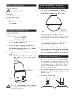
Page 2: ... remove the housing from the packaging material Check to be sure all parts are present 2 This unit includes a 1 NPT housing coupling that can be used with a standard 1 NPT pipe The housing can be used with other brackets designed with 1 male pipe threads such as the UNI WMA1 wall mount bracket 3 Attach the housing coupling to the bracket or pendant pipe Figure 1 NOTE Pipe threads should be clean a...

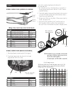
Page 3: ...e power connector yellow and green wire 4 Jumper from the 1st position to the 3 rd position and from the 2nd position to the 4th position of the terminal block Be careful not to short between the yellow and green wires 22 250 120 89 65 44 35 29 25 31 19 17 16 14 13 12 20 400 180 141 90 70 56 47 40 34 31 28 25 23 21 20 18 600 300 225 130 112 90 75 64 55 50 45 41 37 34 32 16 960 480 358 225 179 143 ...

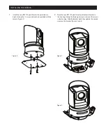
Page 4: ...crews and washers provided with the camera Figure 4 Figure 4 2 Place the Sony BRC700 pan tilt and quick release bracket in the housing sliding the three open screw slots over the screws in the housing Slide the bracket back then tighten the captive screw on the bracket Figures 5 and 6 Figure 5 Figure 6 ...

Page 5: ...he foregoing could result in the unit separating from the support structure and falling with resultant damages or injury to anyone or anything struck by the falling unit IMPORTANT SAFEGUARDS SAFETY PRECAUTIONS UNPACKING SERVICE CAUTION RISK OF ELECTRIC SHOCK DO NOT OPEN CAUTION TO REDUCE THE RISK OF ELECTRIC SHOCK DO NOT REMOVE COVER OR BACK NO USER SERVICEABLE PARTS INSIDE REFER SERVICING TO QUAL...

Page 6: ...ine serves as the geometric center line used to insure proper camera placement It is not typically seen by the camera However Sony RZ series PTZ cameras are able to tilt up above the horizon to 25 this wide range of tilt motion at a wide angle view may cause this line to be captured in the image Warranty For warranty information on this and other Sony Security Systems Products please visit http pr...

Reviews: