background image

In

s

ta

llat
ion
 a

nd 

Conne

c

tio

ns

Installation

55

image may be distorted. This is not malfunction of the 
camera.

Installing the Camera in a  High 
Position

Using the supplied ceiling brackets, wire rope and 
screws, and the attachment materials (not supplied), you 
can attach the camera to a ceiling or on a shelf, etc. in a 
high position. 
When you install the camera, always install it on a level 
ceiling or shelf, etc. If you have to install it on an incline, 
make sure that the inclination is within ± 15 degrees, so 
that the pan/tilt performance is guaranteed.

Before installation

After deciding the shooting direction, make the required 
holes for the ceiling bracket (B) and connecting cables 
on the ceiling or shelf, etc. For the dimensions of the 
ceiling bracket (B), see page 83.

Notes

• The connecting cables cannot be passed through the 

ceiling bracket (A). A hole for the wiring is required 
in the ceiling or on a shelf, etc. behind where the 
camera is to be installed.

• Do not attach any object other than the camera to the 

ceiling brackets.

• The ceiling bracket cannot be attached to the junction 

box when installing the camera on a ceiling.

Installation on a ceiling (example)

1

Set IMG-FLIP to ON in the SYSTEM menu. 
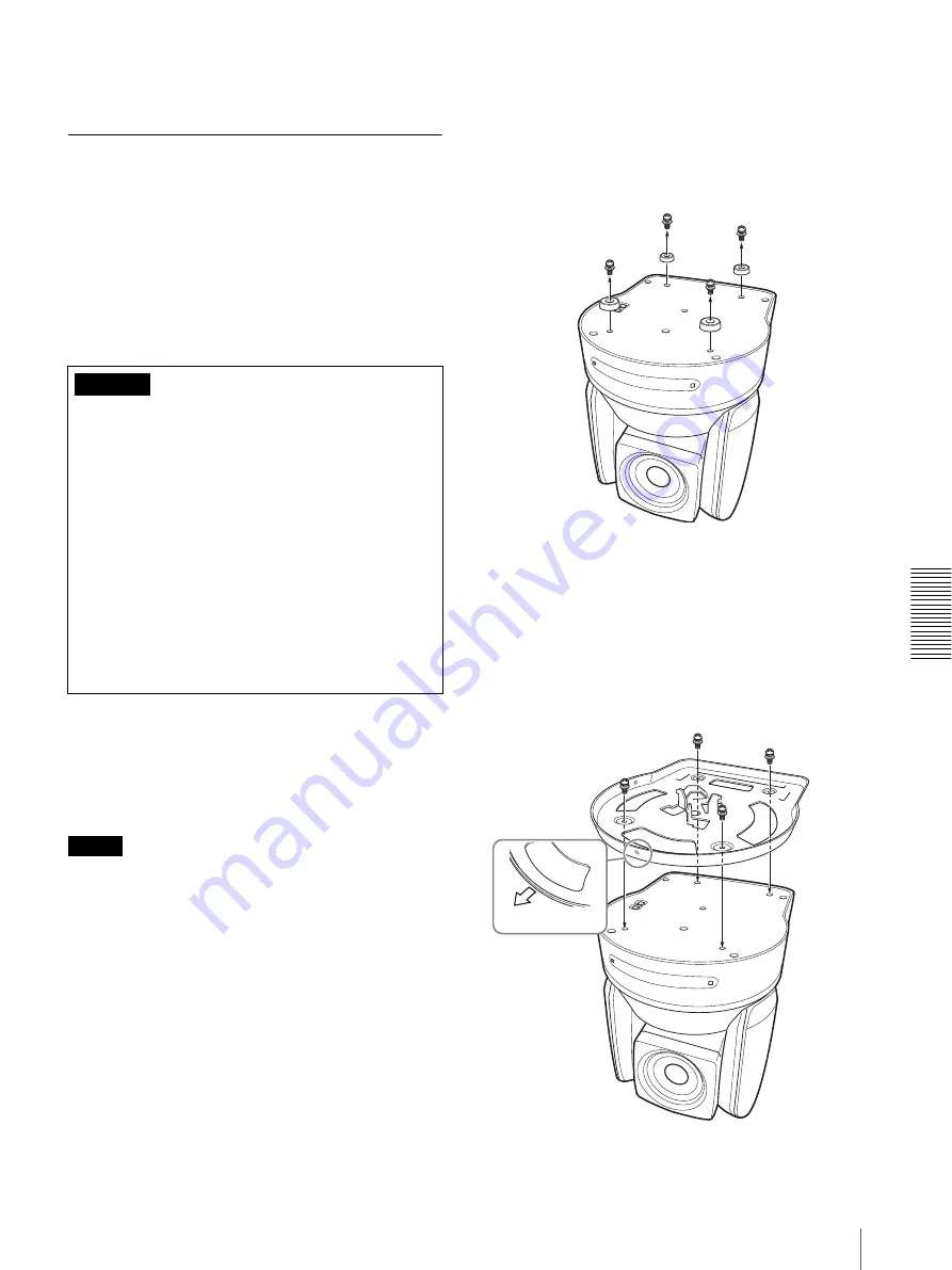
2

Remove the four screws on the bottom of the 
camera to remove the four feet.

3

Attach the ceiling bracket (A) to the bottom of the 
camera using the supplied four screws (

3

M3 × 8).

Position the 

a

 hole for screwing on the ceiling 

bracket (A) to the front of the camera as illustrated, 
align the screw holes on the ceiling bracket with 
those on the bottom of the camera, then attach the 
bracket to the camera.

• When you attach the camera to a ceiling or shelf, etc. 

in a high position, entrust the installation to an 
experienced contractor or installer.

• Attach the camera to the ceiling or shelf, etc. firmly, 

after making sure the ceiling, shelf, etc. and the 
attachment materials (not including the supplied 
accessories) are strong enough to bear a weight of 60 
kg (132 lb 4 oz). If the ceiling or shelf, etc. is not 
strong enough, the camera may fall and cause 
serious injury.

• Be sure to attach the supplied wire rope to prevent 

the camera from falling.

• Check periodically, at least once a year, to ensure 

that the connection has not loosened. If conditions 
warrant, make this periodic check more frequently.

Caution

3

M3 × 8 (supplied)

Ceiling 
bracket (A)

Front of 
camera

Summary of Contents for BRC-Z700 - CCTV Camera

Page 1: ...BRCZ700WW for PrintPDF COVdata 01COV_4 5mm fm masterpage Left BRC H700 3 287 510 11 1 Operating Instructions 3 287 510 11 1 HD 3CMOS Color Video Camera 2007 Sony Corporation BRC Z700 3287510110 Sony Corporation Printed in Japan Printed on recycled paper ...

Page 2: ...energy and if not installed and used in accordance with the instruction manual may cause harmful interference to radio communications Operation of this equipment in a residential area is likely to cause harmful interference in which case the user will be required to correct the interference at his own expense You are cautioned that any changes or modifications not expressly approved in this manual...

Page 3: ... SDI Output Card not supplied available with the BRC Z700 only 25 HFBK SD1 SD Interface Board not supplied available with the BRU H700 only 26 HFBK HD1 HD Interface Board not supplied available with the BRU H700 only 26 HFBK XG1 XGA Interface Board not supplied available with the BRU H700 only 26 HFBK TS1 HDV Interface Board not supplied available with the BRU H700 only 26 Adjusting and Setting Wi...

Page 4: ...ting a Monitor etc Equipped with the Analog Component YPbPr Input Connector 63 Connecting a Device Equipped with VISCA RS 232C Connector 63 Connecting a Device Equipped with VISCA RS 422 Connector 64 Connecting a Video Monitor VTR etc Equipped with Composite Video or S Video Input Connector 65 Connecting a VTR Equipped with SDI Input Connector 65 Connecting a VTR Equipped with HD SDI Input Connect...

Page 5: ...se occurs consult with your Sony dealer Phenomena Specific to CMOS Image Sensors The following phenomena that may appear in images are specific to CMOS Complementary Metal Oxide Semiconductor image sensors They do not indicate malfunctions White flecks Although the CMOS image sensors are produced with high precision technologies fine white flecks may be generated on the screen in rare cases caused...

Page 6: ...rior color reproduction The lens has a focal length of 37 4 mm to 748 mm equivalent to a 35 mm camera Using the optional 0 8 magnification wide conversion lens allows remote shooting of high definition images for various shooting situations Adoption of a 20 magnification optical zoom lens that enables zooming without deterioration in picture quality allows realistic high definition images Built in...

Page 7: ...to make sure it is selected at a glance System Components In order to support multiple system configurations a variety of optional products are available for the BRC Z700 HD 3CMOS Color Video Camera This section introduces these optional products as well as the accessories supplied with the camera Supplied Components and Accessories Before using the camera make sure you have the following componen...

Page 8: ...e Control Unit allows you comfortable pan tilt and zoom operations The Remote Control Unit also allows remote operation of up to seven cameras Supplied accessories AC power adaptor 1 AC power cord 1 RS 232C connecting cable 3 m 1 RS 422 connector plug 2 BRBK MF1 HD Optical Multiplex Card Insert the card into the camera to allow high bit multiplex transfer via optical fiber cable video audio extern...

Page 9: ... connector plug 1 CCFC M100HG Optical Fiber Cable This is a 2 core multi mode optical fiber cable of 100 m 328 feet long Supplied accessories extension plug Video Switcher commercially available It switches the video signal input of multiple cameras VCL HG0862K Wide Conversion Lens The lens is a 0 8 magnification wide conversion lens Optional products for the BRU H700 The Interface Boards describe...

Page 10: ...nalog video signal component RGB An audio signal of the HD SDI signal is not output from the board HFBK XG1 XGA Interface Board The board allows output of a signal conforming to the VESA standards VGA XGA or WXGA HFBK TS1 HDV Interface Board The board allows conversion of the video signal from the camera and the input audio signal into the signal conforming to the HDV standards ...

Page 11: ... Supplied Remote Commander This system allows you To operate the camera readily from a short distance System configuration Operating a BRC Z700 Camera Using the RM BR300 Remote Control Unit This system allows you To perform pan tilt and zoom operations using the joystick of the Remote Control Unit System configuration BRC Z700 Video signal Signal flow Remote Commander supplied HD video monitor VTR...

Page 12: ...you To operate up to seven cameras remotely using a single Remote Control Unit To perform pan tilt and zoom operations using the joystick System configuration Video signal Remote control VISCA signal Tally contact signal Signal flow BRC Z700 BRC Z700 BRC Z700 HD video monitor VTR etc Video switcher RM BR300 Remote Control Unit ...

Page 13: ...to the camera To operate the camera connect the BRU H700 Optical Multiplex Unit to the BRBK MF1 using the CCFC M100HG Optical Fiber Cable and turn on the power of the BRU H700 When the BRBK MF1 HD Optical Multiplex Card is inserted into the BRC Z700 camera the EXT SYNC IN connector VISCA RS 232C IN OUT connectors and VISCA RS 422 connector on the rear of the camera and the BOTTOM switches on the b...

Page 14: ...transmit the video signal and control signal of the cameras to a distant place using the Optical Fiber Cable System configuration BRC Z700 BRC Z700 BRC Z700 BRBK MF1 HD Optical Multiplex Card BRBK MF1 BRBK MF1 BRU H700 Optical Multiplex Unit BRU H700 HD video monitor VTR etc BRU H700 Video switcher RM BR300 Remote Control Unit CCFC M100HG Optical Fiber Cable CCFC M100HG CCFC M100HG Video signal Re...

Page 15: ...perations using the joystick To control the BRC Z700 cameras remotely from a distance up to 1 000 m 3 281 feet by transmitting the video signal and control signal using the Optical Fiber Cable System configuration VISCA controllable camera BRC Z700 BRC Z700 BRBK MF1 BRBK MF1 HD Optical Multiplex Card HD video monitor VTR etc BRU H700 Video switcher RM BR300 Remote Control Unit CCFC M100HG Optical ...

Page 16: ...gnal and control signal of the camera and the audio signal input to the BRBK MF1 Optical Multiplex Card to a distant place using the Optical Fiber Cable System configuration BRC Z700 Microphone HD video monitor RM BR300 Remote Control Unit CCFC M100HG Optical Fiber Cable Video signal Audio line signal Remote control VISCA signal Signal flow Microphone amplifier BRBK MF1 HD Optical Multiplex Card S...

Page 17: ...e video signal delay in this system is caused by signal processing in the HFBK TS1 HDV Interface Board If you are uncomfortable with the delay output the video signal via the RGB COMPONENT connector on the BRU H700 You cannot operate pan tilt and zoom with HDV video equipment connected to the i LINK HDV OUT connector on the HFBK TS1 HDV Interface Board Use the VISCA RS 232C or VISCA RS 422 connect...

Page 18: ...tion to the VISCA RS 422 connector see Using the VISCA RS 422 Connector Plug on page 90 H 75 ohm termination switch This switch is used when an external sync signal is used Set it to OFF when this camera is in the middle of a daisy chain connection of multiple cameras Set it to ON when the camera is at the end of a daisy chain connection or when nothing is connected to the EXT SYNC IN connector on...

Page 19: ... for the output signal format selection RS 232C RS 422 selection baud rate selection remote control signal output on off and camera address setting For details see Setting of the BOTTOM switches on page 19 Setting of the BOTTOM switches 1 Switch 1 59 94i 50i signal format selector Set to ON for output of 50i signal format or OFF for output of 59 94i signal format 2 Switch 2 RS 232C RS 422 selector...

Page 20: ... face the camera back to the front When the menu is displayed use V or v to select the menu items and B or b to change the set values E L R DIRECTION SET button Hold down this button and press the REV button to change the direction of the camera movement opposite to that indicated by the arrow of the B b buttons To reset the direction of the camera movement press the STD button while holding down ...

Page 21: ...lected on the camera For details see Functions of the R and B controls on page 50 C BRIGHT B control When the brightness adjustment mode is selected with the MODE button with the BRIGHT indicator lit Adjusts the value of the brightness of the camera etc When the BRIGHT indicator is lit the function of the control varies according to the MODE setting in the EXPOSURE menu of the camera For details s...

Page 22: ...ALANCE menu of the camera press this button to perform the one push white balance adjustment N MENU button Press this button for about one second to display or turn off the menu of the camera or return to the main menu O Joystick When the menu of the camera is not displayed The joystick is used for pan tilt and zoom operations When you incline the joystick right and left the camera pans When you i...

Page 23: ...selector Select the function of the TALLY CONTACT connector TALLY The tally lamp of the camera selected with the connected switcher lights CONTACT The contact output corresponding to the camera address selected with the Remote Control Unit is short circuited against the connected switcher CONTACT TALLY The contact output corresponding to the camera address selected with the Remote Control Unit is ...

Page 24: ...t of the audio line signal input from the AUDIO IN jacks on the BRBK H700 HD Optical Multiplex Card inserted into the camera via the Optical Fiber Cable F AC IN connector Connect the supplied AC power cord G CAMERA connector Connect to the optical connector of the BRBK H700 HD Optical Multiplex Card installed in the BRC H700 camera using the CCFC M100HG Optical Fiber Cable A dustproof cap is attac...

Page 25: ... which is output from the AUDIO OUT jacks on the BRU H700 HD Optical Multiplex Unit via the Optical Fiber Cable Note The audio input on this board accepts audio line signals only When you input audio signals from a microphone etc it should be connected with a microphone amplifier so that audio signals with an appropriate audio level can be input B Optical connector Performs the optical digital mul...

Page 26: ...an be selected in the HD SDI menu of the camera B DIP switches inside the cap When this Interface Board is inserted into the BRU H700 HD Optical Multiplex Unit the DIP switches cannot be used C HD SDI connector BNC type Supplies HD SDI signals that conform to the SMPTE292M serial digital interface standards The two connectors output the same signal HFBK XG1 XGA Interface Board not supplied availab...

Page 27: ...audio signals after they are converted to comply with HDV standards Note The audio input on this board accepts audio line signals only When you input audio signals from a microphone etc it should be connected with a microphone amplifier so that audio signals with an appropriate audio level can be input ...

Page 28: ... V or v button on the Remote Commander or by inclining the joystick of the RM BR300 Remote Control Unit forward or backward 2 Menu items To display a setting menu select one using the V or v button on the Remote Commander or the joystick of the RM BR300 Remote Control Unit and press the HOME button on the Remote Commander or the top button of the joystick on the RM BR300 3 Page number Displays the...

Page 29: ... joystick of the RM BR300 Remote Control Unit For the default value of each setting item see Menu Configuration on page 73 Operation Through Menus This section explains how to operate the menu using the supplied Remote Commander or using the RM BR300 Remote Control Unit not supplied For details on each menu see pages 31 through 41 Menu Operation Using the Supplied Remote Commander 1 Press the DATA...

Page 30: ...l Unit 1 Press the MENU button for about one second PAGE 1of the main menu appears To display PAGE2 of the main menu press the MENU button again 2 Move the cursor to the menu item to be set by inclining the joystick forward or backward 3 Press the button on the top of the joystick The selected menu appears SYSTEM IR RECEIVE IMG FLIP PAN REVERSE TILT REVERSE DISPLAY INFO SYNC MASTER H PHASE ON OFF ...

Page 31: ...ed Adjust the iris IRIS manually GAIN Pri Sensitivity Priority mode The exposure is adjusted automatically using the iris and electronic shutter speed Adjust the sensitivity GAIN manually When you select MODE some of the following setting items that are required for the selected mode appear AE SPEED Select the exposure adjustment speed at which an optimum exposure value is obtained automatically Y...

Page 32: ...hite balance mode Select the white balance mode from among the following AUTO1 AUTO2 INDOOR OUTDOOR ONE PUSH MANUAL AUTO1 Adjusts the white balance automatically while leaving natural colors AUTO2 Adjusts the white balance automatically INDOOR The R GAIN and B GAIN values are fixed to those for a color temperature of 3200K OUTDOOR The R GAIN and B GAIN values are fixed to those for a color tempera...

Page 33: ...level The adjustable level is in the range of 0 to 15 The larger the setting level the sharper the image outline You can obtain the softest image outline by selecting level 0 COLOR DETAIL Reduces the image enhancer of a specific color NARROW The region of the color specified with PHASE becomes narrow STD The region of the color specified with PHASE is that between NARROW and WIDE WIDE The region o...

Page 34: ... of the camera is displayed on the monitor screen FOCUS Menu The FOCUS menu is used to select the focus mode MODE focus mode Select the focus adjustment mode AUTO The focus is adjusted automatically MANUAL Adjust the focus manually Use the FAR NEAR buttons on the supplied Remote Commander to adjust the focus Note Set MODE to MANUAL when you shoot a flat subject with low contrast such as a white wa...

Page 35: ...IT setting If the camera position is not within the range of the PAN TILT LIMIT setting you cannot store the camera position in the preset memory The PAN TILT LIMIT setting is reset to the factory setting when you change IMG FLIP of the SYSTEM menu RAMP CURVE Select the panning and tilting speed acceleration or reduction mode when the preset panning and tilting operation is recalled MODE1 Panning ...

Page 36: ... RGB COMPONENT connector upside down and to reverse the direction of the camera movement by pan tilt operation Set PAN REVERSE to ON to reverse the horizontal movement of the camera image Set TILT REVERSE to ON to reverse the vertical movement of the camera image When you set IMG FLIP to ON Please restart system appears Turn off the power of the camera and turn it on again Notes Regardless of the ...

Page 37: ...ect a sync signal generator adjust the horizontal phase so that the output signal is synchronized with the external sync signal input to the camera The adjustable range is from 0 to 140 When you select H PHASE in the menu the color bar is displayed on the screen Then perform the H PHASE adjustment After completing the adjustment press the HOME button on the Remote Commander or the button on the to...

Page 38: ...hem with the menu PAGE1 Shows the settings selected with the EXPOSURE menu PAGE2 Shows the settings selected with the COLOR menu PAGE3 Shows the settings selected with the PICTURE menu PAGE4 Shows the settings selected with the SYSTEM and FOCUS menus PAGE5 Shows the settings selected with the PAN TILT ZOOM menu PAGE6 Shows the settings selected with the VIDEO OUT menu status of the fan motors the ...

Page 39: ...bPr Outputs analog component signals RGB Outputs RGB signals ADD SYNC Appears when RGB is selected with D SUB OUT1 and specifies whether to add a sync signal RGB Outputs each R G and B signal with a sync signal added G Outputs the G signal with a sync signal added OFF Outputs each signal with no sync signal added D SUB OUT2 Select the output signal from the MONITOR connector on the HFBK SD1 SD Int...

Page 40: ...tput from the MONITOR connector D sub 15 pin on the HFBK HD1 HD Interface Board YPbPr Outputs analog component signals RGB Outputs RGB signals SYNC VD Select the signal output from the SYNC output on the MONITOR connector SYNC Outputs the tri level sync VD Outputs the bi level sync ADD SYNC Appears when RGB is selected with ANALOG OUT and specifies whether to add a sync signal RGB Outputs each R G...

Page 41: ... G signal with a sync signal added OFF Outputs the G signal with no sync signal added VD Select the VD polarity according to the monitor to be used POS Positive NEG Negative HDV Menu The HDV menu is displayed only when the HFBK TS1 HDV Interface Board is inserted into the card slot of the BRU H700 HD Optical Multiplex Unit AUDIO DELAY Compensates for the delay between the video signal output from ...

Page 42: ...o move the camera diagonally press the B or b button while holding down the V or v button To face the camera back to the front Press the HOME button If you accidentally move the camera with your hand Press the PAN TILT RESET button to perform the pan tilt reset action If the camera moves in a different direction from that you intended The camera is preset to face toward the right whenever the b bu...

Page 43: ... in the telephoto mode the moving speed of the image on the screen may be a little jerky Operating Multiple Cameras with the Remote Commander 1 Set the IR SELECT switch on the rear of the camera you want to operate to 1 2 or 3 2 Press the CAMERA SELECT button on the Remote Commander that corresponds to the number set in step 1 Then you can operate the camera s specified by number Every time you op...

Page 44: ...se press the BACK LIGHT button To cancel the function press the BACK LIGHT button again Note The BACK LIGHT function is not effective if MODE is set to MANUAL in the EXPOSURE menu of the camera P O W E R C A M E R A S E L E C T 1 2 3 A U T O P O S IT IO N H O M E R M E V 1 0 0 R E S E T P R E S E T S T D R E V F A R F O C U S W T W T 1 2 3 4 5 6 P A N T IL T S L O W F A S T Z O O M L R D IR E C T ...

Page 45: ...s any of the POSITION buttons 1 to 6 in which you have stored the settings To cancel the preset memory While holding down the RESET button press the POSITION button from which you want to cancel the settings Notes When the power is turned on the camera starts with the settings stored in POSITION 1 If you want to retain the previous pan and tilt positions etc when the power is turned off and turned...

Page 46: ...on the Remote Control Unit While holding down the POWER button press the CAMERA button corresponding to the camera whose power you want to turn on off When you turn the power off using the Remote Control Unit the POWER lamp turns off and the STANDBY lamp lights on the camera To illuminate the panel of the Remote Control Unit Press the PANEL LIGHT button All the POSITION buttons and CAMERA buttons ...

Page 47: ...utomatically 2 Press the CAMERA button corresponding to the camera you want to operate 3 Operate the joystick to pan or tilt the camera While checking the picture on the screen incline the joystick in the desired direction The panning tilting speed changes according to the angle at which you incline the joystick Release the joystick to stop panning tilting To set a limit on the maximum panning til...

Page 48: ... toward the opposite direction from that in which you inclined the joystick for example when you change the direction of the camera while checking the picture on the screen In such a case press the POSITION 2 REV button while holding down the L R DIRECTION button To reset the setting press the POSITION 1 STD button while holding down the L R DIRECTION button Note The setting above only changes the...

Page 49: ...at the AUTO indicator turns off Then turn the FOCUS control clockwise or counterclockwise to have the camera focus on the subject One push auto focusing during manual focus adjustment Press the ONE PUSH AF button The camera focuses on the subject in the center of the screen automatically Subject appears farther away Wide angle Subject appears closer Telephoto MODE 1 1 9 LOCK MODE VALUE RESET MENU ...

Page 50: ...ss the ONE PUSH AWB button The white balance is adjusted automatically To adjust the white balance manually 1 Set WHITE BALANCE to MANUAL in the COLOR menu of the camera For setting see COLOR Menu on page 32 2 Press the MODE button so that the R and B indicators on the VALUE R and BRIGHT B controls light White balance adjustment mode 3 Adjust the red gain with the R control and the blue gain with ...

Page 51: ...ress the CAMERA button to select the camera whose settings you want to preset 3 Adjust the position zooming focusing and backlighting of the camera See page 47 to 50 MODE setting Function of VALUE control Function of BRIGHT control FULL AUTO Not used Exposure compensation level control SHUTTER Pri Shutter speed control Exposure compensation level control IRIS Pri F number control Exposure compensa...

Page 52: ...ION 1 When you are storing or canceling the settings in one POSITION you cannot call up store or cancel the settings in another POSITION Setting the Speed of the Camera Moving to a Preset Position You can select the panning tilting speed when the camera moves to a preset position 1 Press the CAMERA button to select the camera whose speed you want to set 2 Press the POSITION button for which you wa...

Page 53: ...ert an optional Interface Board into the card slot Align both ends of the Interface Board with the sliders inside the slot then insert the board securely as far as it will go 3 Tighten the two screws on the Interface Board To remove the Interface Board Loosen the two screws on the Interface Board and pull the board out straight and slowly Installing the Camera To install the camera on a desk Place...

Page 54: ...he lens counterclockwise until it clicks while pressing the release button then remove the lens while holding the release button Caution To prevent the wide conversion lens from falling be sure to pay attention to the following Check that the lens will not turn after attaching it to the camera Do not use the camera with the wide conversion lens attached in locations subject to strong vibration or ...

Page 55: ... junction box when installing the camera on a ceiling Installation on a ceiling example 1 Set IMG FLIP to ON in the SYSTEM menu 2 Remove the four screws on the bottom of the camera to remove the four feet 3 Attach the ceiling bracket A to the bottom of the camera using the supplied four screws 3M3 8 Position the a hole for screwing on the ceiling bracket A to the front of the camera as illustrated...

Page 56: ...head cap screw not supplied Attach the wire rope to an area independent of the area where the ceiling bracket is attached 6 Attach the wire rope to the ceiling bracket A Pass the wire rope through the fixing hole and attach its end to the attachment hole on the bracket using the supplied one screw 3M4 8 Ceiling bracket B f hole Ceiling Attachment materials Ceiling bracket B Ceiling Attachment mate...

Page 57: ...rackets A and B using the supplied three screws 3M3 8 9 Connect the cables to the connectors on the rear of the camera Note Take the proper steps to ensure that the load of the cables connected does not cause problems 10 The SONY and or HD nameplates can be turned upside down if necessary To remove the camera 1 Remove the three screws used to attach the camera in step 8 of Installation on a ceilin...

Page 58: ...ttom of the camera then attach the bracket to the camera Note For attaching the camera to the ceiling bracket use only the supplied screws Using other screws may damage the camera 3 Attach the supplied wire rope to the ceiling bracket A Pass the wire rope through the fixing hole and attach its end to the attachment hole on the bracket using the supplied one screw 3M4 8 3M3 8 supplied Ceiling brack...

Page 59: ... the direction where the front of the camera will be positioned later 5 Attach the other end of the wire rope to the material near the shelf etc Use an M5 3 16 inch hexagon socket head cap screw not supplied Attach the wire rope to the material independent of the shelf etc where the ceiling bracket B is attached Ceiling bracket B f hole Wall Shelf etc Screws 4 Hole for connecting cables M5 3 16 in...

Page 60: ...bracket B with the a hole in the front of the ceiling bracket A aligned with the hole on the ceiling bracket B and temporarily attach them by turning the ceiling bracket A with the camera counterclockwise 7 Secure the ceiling brackets A and B using the supplied three screws 3M3 8 Ceiling bracket B Align Ceiling bracket A 3M3 8 supplied ...

Page 61: ...ra in step 7 of Installation on a shelf etc in a high position example 2 Turn the camera with the bracket clockwise to remove Connections Connecting to an AC Outlet Use the supplied AC power adaptor and AC power cord to connect the camera to an AC outlet RGB COMPONENT VISCA RS 422 1 2 3 4 5 6 7 8 9 EXT SYNC IN VIDEO IR SELECT 75 1 2 3 OFF ON DATA MIX OFF ON IN VISCA RS 232C OUT S VIDEO DC IN 12V R...

Page 62: ...the VISCA RS 422 connector pages 86 and 87 and the wiring diagram of VISCA RS 422 connection page 89 For the use of the RS 422 connector plugs see page 90 Notes When using the VISCA RS 422 connectors check that the BOTTOM switch on the bottom of the camera page 19 and the DIP switch on the bottom of the Remote Control Unit page 23 are set to RS 422 When the connections using the VISCA RS 422 conne...

Page 63: ...eo input HD video monitor etc RGB COMPONENT VISCA RS 422 1 2 3 4 5 6 7 8 9 EXT SYNC IN IR SELECT 75 1 2 3 OFF ON DATA MIX OFF ON IN VISCA RS 232C OUT DC IN 12V R VISCA RS 422 1 2 3 4 5 6 7 8 9 EXT SYNC IN IR SELECT 75 1 2 3 OFF ON DATA MIX OFF ON IN VISCA RS 232C OUT DC IN 12V R VISCA RS 422 1 2 3 4 5 6 7 8 9 EXT SYNC IN IR SELECT 75 1 2 3 OFF ON DATA MIX OFF ON IN VISCA RS 232C OUT DC IN 12V R VI...

Page 64: ...onnectors check that the BOTTOM switch on the bottom of the camera page 19 and the DIP switch on the bottom of the Remote Control Unit page 23 are set to RS 422 When the connections using the VISCA RS 422 connectors are made the VISCA RS 232C connection is not available Do not make the VISCA RS 422 connection and the VISCA RS 232C connection simultaneously If both cables are connected simultaneous...

Page 65: ...ge 39 Note Signal processing in the output card causes all output signals from the BRBK HSD1 to be delayed by approximately 93H horizontal sync time compared with the YPbPr RGB output signals from the camera A similar delay occurs when using an external sync signal RGB COMPONENT VISCA RS 422 1 2 3 4 5 6 7 8 9 EXT SYNC IN IR SELECT 75 1 2 3 OFF ON DATA MIX OFF ON IN VISCA RS 232C OUT DC IN 12V R VI...

Page 66: ...era cannot be used When using the VISCA RS 232C connectors or VISCA RS 422 connectors check the VISCA FUNCTION switch on the rear of the Optical Multiplex Unit page 25 and the DIP switch on the RGB COMPONENT VISCA RS 422 1 2 3 4 5 6 7 8 9 EXT SYNC IN IR SELECT 75 1 2 3 OFF ON DATA MIX OFF ON IN VISCA RS 232C OUT DC IN 12V R VIDEO S VIDEO HD SD BRBK HSD1 HD SD SDI Output Card to AC outlet SDI OUTPU...

Page 67: ...IN VISCA RS 232C OUT DC IN 12V R RGB COMPONENT VISCA RS 422 1 2 3 4 5 6 7 8 9 EXT SYNC IN IR SELECT 75 1 2 3 OFF ON DATA MIX OFF ON IN VISCA RS 232C OUT DC IN 12V R RGB COMPONENT VISCA RS 422 1 2 3 4 5 6 7 8 9 EXT SYNC IN IR SELECT 75 1 2 3 OFF ON DATA MIX OFF ON IN VISCA RS 232C OUT DC IN 12V R VIDEO S VIDEO VIDEO S VIDEO VIDEO S VIDEO MODE VISCA 1 9 1 9 RS 422 ON OFF TALLY CONTACT RS 232C CONTAC...

Page 68: ...N IR SELECT 75 1 2 3 OFF ON DATA MIX OFF ON IN VISCA RS 232C OUT DC IN 12V R RGB COMPONENT VISCA RS 422 1 2 3 4 5 6 7 8 9 EXT SYNC IN IR SELECT 75 1 2 3 OFF ON DATA MIX OFF ON IN VISCA RS 232C OUT DC IN 12V R RGB COMPONENT VISCA RS 422 1 2 3 4 5 6 7 8 9 EXT SYNC IN IR SELECT 75 1 2 3 OFF ON DATA MIX OFF ON IN VISCA RS 232C OUT DC IN 12V R VIDEO S VIDEO VIDEO S VIDEO VIDEO S VIDEO Second BRC Z700 7...

Page 69: ... RS 422 1 2 3 4 5 6 7 8 9 EXT SYNC IN IR SELECT 75 1 2 3 OFF ON DATA MIX OFF ON IN VISCA RS 232C OUT DC IN 12V R RGB COMPONENT VISCA RS 422 1 2 3 4 5 6 7 8 9 EXT SYNC IN IR SELECT 75 1 2 3 OFF ON DATA MIX OFF ON IN VISCA RS 232C OUT DC IN 12V R VIDEO S VIDEO VIDEO S VIDEO VIDEO S VIDEO Second BRC Z700 75 ohm termination switch ON to AC outlet to AC outlet 75 ohm termination switch OFF First BRC Z7...

Page 70: ...STEM menu To exit from the adjustment press the HOME button on the Remote Commander or the button on the top of the joystick on the Remote Control Unit PUSH ENTER BUTTON This message appears when you move the cursor to H PHASE in the SYSTEM menu To start the H PHASE adjustment press the HOME button on the Remote Commander or the button on the top of the joystick on the Remote Control Unit PRESET x...

Page 71: ... in the EXPOSURE menu Pan tilt or zoom cannot be operated Any menu is displayed on the monitor screen Press the DATA SCREEN button on the supplied Remote Commander or the MENU button on the RM BR300 Remote Control Unit to turn off the menu from the monitor screen The panning or tilting range is limited Change the PAN TILT LIMIT setting in the PAN TILT ZOOM menu page 35 The Remote Commander does no...

Page 72: ... the DIP switch on the Remote Control Unit page 23 Try to connect the camera to the RM BR300 Remote Control Unit to check that the camera works properly The picture quality obtained from the camera connected to a computer differs from that from the camera connected to a video monitor Depending on your computer or video capture board you may not be able to obtain the expected picture quality Consul...

Page 73: ... 1 1250 1 1750 1 2500 1 3500 1 6000 1 10000 50i IRIS F1 6 F1 7 F1 8 F2 0 F2 2 F2 4 F2 6 F2 8 F3 1 F3 7 F4 0 F4 4 F4 8 F5 2 F5 6 F6 2 F6 8 F7 3 F8 0 F8 7 F9 6 F10 F11 F12 F14 F15 F16 CLOSE SHUTTER Pri SPEED 1 60 1 90 1 100 1 125 1 180 1 250 1 350 1 500 1 725 1 1000 1 1500 1 2000 1 3000 1 4000 1 6000 1 10000 59 94i 1 50 1 75 1 100 1 120 1 150 1 215 1 300 1 425 1 600 1 1000 1 1250 1 1750 1 2500 1 350...

Page 74: ...X ON PAGE1 R ENHANCE 10 9 8 7 6 5 4 3 2 1 0 1 2 3 4 5 6 7 8 9 10 G ENHANCE 10 9 8 7 6 5 4 3 2 1 0 1 2 3 4 5 6 7 8 9 10 B ENHANCE 10 9 8 7 6 5 4 3 2 1 0 1 2 3 4 5 6 7 8 9 10 ON PAGE2 YL ENHANCE 10 9 8 7 6 5 4 3 2 1 0 1 2 3 4 5 6 7 8 9 10 CY ENHANCE 10 9 8 7 6 5 4 3 2 1 0 1 2 3 4 5 6 7 8 9 10 MG ENHANCE 10 9 8 7 6 5 4 3 2 1 0 1 2 3 4 5 6 7 8 9 10 OFF page 32 PICTURE DETAIL 0 1 2 3 4 5 6 7 8 9 10 11 ...

Page 75: ...0 page 35 SYSTEM IR RECEIVE ON OFF IMG FLIP ON OFF PAN REVERSE ON OFF TILT REVERSE ON OFF DISPLAY INFO ON OFF SYNC MASTER STD HD STD SD HD1 SD1 H PHASE 0 10 140 page 36 VIDEO OUT HD RGB COMPONENT FORMAT YPbPr SYNC TYPE SYNC VD RGB ADD SYNC RGB OFF SYNC TYPE SYNC VD SD VIDEO S VIDEO IMG SIZE 16 9 LETTER 4 3 CROP 4 3 SQUEEZE SETUP ON OFF Does not appear when an output signal is 50i format page 37 ...

Page 76: ...HANCE R G B YL CY MG PAGE 3 DETAIL COLOR DETAIL PHASE GAMMA FLICKER CANCEL STEADY SHOT OFF B W COLOR BAR PAGE 4 FOCUS MODE NEAR LIMIT AF ASSIST IR RECEIVE IMG FLIP REVERCE DISPLAY OFF SYNC MASTER H PHASE PAGE 5 PAN TILT LIMIT PAN LEFT RIGHT TILT DOWN UP RAMP CURVE D ZOOM PAGE 6 HD FORMAT RGB SYNC SYNC TYPE SD IMAGE SIZE SETUP FAN MOTOR BRC VERSION BRU VERSION page 38 Appears only when the BRU H700...

Page 77: ...T 2 VBS Y C IMG SIZE 16 9 LETTER 4 3 CROP 4 3 SQUEEZE SETUP OFF ON page 39 Does not appear when an output signal is 50i format HD SDI ANALOG OUT YPbPr SYNC VD SYNC VD RGB SYNC VD SYNC VD ADD SYNC RGB OFF page 40 PC OUTPUT IMG SIZE XGA CROP VGA LETTER XGA LETTER VGA CROP WXGA SYNC OFF ON VD POS NEG page 41 HDV AUDIO DELAY OFF 1STEP 2STEP 3STEP 4STEP 5STEP 6STEP 7STEP 8STEP 9STEP 10STEP page 41 ...

Page 78: ...a a a a a a a a a GAIN Pri VAL z a a a a a a a a a a a a a a a EX COMP MODE z a a a a a a a a a a a a a a a EX COMP VAL z a a a a a a a a a a a a a a a BACK LIGHT z a a a a a a a a a a a a a a a SPOT LIGHT z a a a a a a a a a a a a a a a WHITE BALANCE MODE z a a a a a a a a a a a a a a a WB SENS z a a a a a a a a a a a a a a a WB R SHIFT AUTO z a a a a a a a a a a a a a a a WB B SHIFT AUTO z a a a...

Page 79: ... a a a a a a a a a a a a a a a NEAR LIMIT f AF ASSIST f PAN LIMIT MODE f TILT LIMIT MODE f PAN LIMIT AREA f TILT LIMIT AREA f RAMP CURVE f D ZOOM z IR RECEIVE f IMG FLIP2 f PAN REVERSE f TILT REVERSE f DISPLAY INFO f SYNC MASTER f H PHASE f FORMAT HD OUTPUT f ADD SYNC f SYNC TYPE f IMG SIZE f SETUP not available for 50i output signal f Menu items displayed only when the BRBK HSD1 is installed IMG ...

Page 80: ...tained in memory only when the power is turned on Setting items cleared from the memory when the power is turned off and on Menu items displayed only when the HFBK HD1 is installed ANALOG OUT f SYNC VD f ADD SYNC f Menu items displayed only when the HFBK XG1 is installed IMG SIZE f SYNC f VD f Menu items displayed only when the HFBK TS1 is installed AUDIO DELAY f Menu item Presetting position numb...

Page 81: ...evel sync at 75 ohm termination Component Y 1 Vp p 0 3 V tri level sync at 75 ohm termination Pb Pr 350 mVp p 75 ohm terminated HD VD Sync 1 Vp p 75 ohm terminated Tri level Sync 300 mVp p 75 ohm terminated VIDEO BNC type Composite 1 Vp p sync negative at 75 ohm termination S VIDEO mini DIN 4 pin S video output Y 1 Vp p sync negative at 75 ohm termination C Same as chroma level of composite signal...

Page 82: ...ut notice Note Always verify that the unit is operating properly before use SONY WILL NOT BE LIABLE FOR DAMAGES OF ANY KIND INCLUDING BUT NOT LIMITED TO COMPENSATION OR REIMBURSEMENT ON ACCOUNT OF THE LOSS OF PRESENT OR PROSPECTIVE PROFITS DUE TO FAILURE OF THIS UNIT EITHER DURING THE WARRANTY PERIOD OR AFTER EXPIRATION OF THE WARRANTY OR FOR ANY OTHER REASON WHATSOEVER ...

Page 83: ...2 238 9 3 8 99 4 58 2 3 8 98 3 7 8 149 5 7 8 51 2 1 8 98 3 7 8 102 4 1 8 ø186 7 3 8 ø161 63 8 30 90 30 50 2 5 0 2 5 0 2 20 1 3 1 6 2 0 20 13 16 20 13 16 4 ø4 2 hole 23 1 15 16 ø8 2 11 32 30 1 3 16 Unit mm inches Front Bottom Side Top Ceiling Bracket B Side Top Tripod screw hole h o l e ...

Page 84: ...IRECTION PANEL LIGHT BLACK LIGHT PAN TILT RESET ONE PUSH AWB POWER AUTO MANUAL AUTO ONE PUSH AF 2 3 4 5 6 7 2 10 STD REV 3 11 4 POSITION CAMERA 12 5 13 6 14 7 15 8 16 R BRIGHT B FOCUS NEAR FAR 145 9 5 3 4 137 2 5 1 2 391 3 15 1 2 45 9 1 13 16 185 7 3 8 30 30 Unit mm inches Front Bottom Side Top DIP switches ...

Page 85: ...Appendix Specifications 85 BRU H700 HD Optical Multiplex Unit 210 8 3 8 240 9 1 2 94 3 3 4 86 3 1 2 86 3 1 2 Unit mm inches Front Top Side ...

Page 86: ...GND 7 SIRCS OUT 8 No Connection 1 2 3 4 5 VISCA RS 422 6 7 8 9 IN VISCA RS 232C Pin No Function 1 DTR OUT 2 DSR OUT 3 TXD OUT 4 GND 5 RXD OUT 6 GND 7 No Connection 8 No Connection Pin No Function At YPbPr COMPONENT setting At YPbPr COMPONENT setting at VD At RGB setting at SYNC At RGB setting at VD 1 Pr OUT Pr OUT R OUT R OUT 2 Y OUT Y OUT G OUT G OUT 3 Pb OUT Pb OUT B OUT B OUT 4 GND GND GND GND ...

Page 87: ... female Pin No Function 1 No Connection 2 No Connection 3 TXD IN 4 GND 5 RXD IN 6 GND 7 No Connection 8 No Connection Pin No Function 1 No Connection 2 No Connection 3 No Connection 4 No Connection 5 GND 6 RXD IN 7 RXD IN 8 TXD IN 9 TXD IN RS 232C VISCA 1 9 RS 422 Pin No Function 1 CAMERA1 2 CAMERA2 3 CAMERA3 4 CAMERA4 5 CAMERA5 6 CAMERA6 7 CAMERA7 8 GND 9 GND Pin No Function 1 DTR IN 2 DSR IN 3 T...

Page 88: ...TXD IN VISCA RS 232C OUT VISCA RS 422 1 2 3 4 5 6 7 8 9 Pin No Function At YPbPr COMPONENT setting At YPbPr COMPONENT setting at VD At RGB setting at SYNC At RGB setting at VD 1 Pr OUT Pr OUT R OUT R OUT 2 Y OUT Y OUT G OUT G OUT 3 Pb OUT Pb OUT B OUT B OUT 4 GND GND GND GND 5 GND GND GND GND 6 GND GND GND GND 7 GND GND GND GND 8 GND GND GND GND 9 NC NC NC NC 10 GND GND GND GND 11 GND GND GND GND ...

Page 89: ...D IN 9 TXD IN 1 RXD OUT 2 RXD OUT 3 TXD OUT 4 TXD OUT 5 GND 6 RXD IN 7 RXD IN 8 TXD IN 9 TXD IN 1 NC 2 NC 3 NC 4 NC 5 GND 6 RXD IN 7 RXD IN 8 TXD IN 9 TXD IN RM BR300 Remote Control Unit VISCA RS 422 connector NC No Connection Third to Seventh BRC Z700 or BRU H700 VISCA RS 422 connector Second BRC Z700 or BRU H700 VISCA RS 422 connector First BRC Z700 camera or BRU H700 HD Optical Multiplex Unit V...

Page 90: ...connector To remove the connector plug Grasp both ends of the VISCA RS 422 connector plug and pull it out as shown in the illustration Notes In order to stabilize the voltage level of the signal connect both ends to GND When the connections using the VISCA RS 422 connectors are made the VISCA RS 232C connection is not available The maximum connection distance with the VISCA RS 422 connection is ap...

Page 91: ......

Reviews: