RB1G
CHASSIS
W900A/904A/905A
SECTION 4
SERVICE ADJUSTMENTS
4-1. Accessing Service Mode
1) Go to TV standby condition by remote commander.
2) Press “i+ (info)”, “5”, “” then “TV power” on remote.
3)
You can see Service Mode on display.
1. Change Data of
“Chassis”
or
“VPC”
service mode
a.
Press “2 / 5” on remote to select (up / down) category.
b
Press “1 / 4” on remote to select (up / down) Item
4-3. Change Data by Service Mode 1
DIGITAL SERVICE
001 OP
000 VERS ---
* The above operation should be finished within 15 seconds after
the set go to STBY
mode
TV Power
4
b.
Press 1 / 4 on remote to select (up / down) Item.
c.
Press “3 / 6” on remote to change (up / down) data.
Press 2: increment
Press 5: decrement
<MAIN> <EXT>
DM1.301W00AA WF:2.0.0.99
WF1.003W00AA WF:--------
DF1.001W00AA FD:0.068
YM1.010W00AA BT:
M4 922C
1 2 14 891
(i+)
Vol (+)
1
2
CHASSIS
SERVICE
000
WYVERN
000
S2_NOISE_TH 32
Press 1: increment
Press 3: increment
a
b
c
M4.922C
1.2.14.891
(DM1.301W00AA)
DD1.016W00AA
PK0.312W00AA
AM0.510WW
MID:04835511
PID 04020000
Remote Commander
Vol (+)
2
3
Press 1: increment
Press 4: decrement
Press 3: increment
Press 6: decrement
CHASSIS Service menu
PID:04020000
PNL:LTY320AB01
DQ3Y550LN0101
Remote Commander
Screen Sample
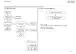
4-2. Transition of Each Micro’s Service Mode
1
Fi t f ll
h
t
S
i
M d
4-4.Save Changing Data by Service Mode 1
2.
Write data for
“Chassis”
or
“VPC”
service mode.
a.
Press “Mute” on remote.
It shows green “SERVICE” changes to green
OPTIONS
1.
First of all, when you enter Service Mode, you can
see “Digital” service mode.
2.
Whenever you press “OPTIONS” on remote, service
mode is changed according to the flow below:
“WRITE”.
b.
Press “0” on remote. Green “WRITE” changes to
red “WRITE”. It indicate writing is processing.
c.
After a while, red “WRITE” changes to green
“SERVICE”. Writing process is done at this point.
3
TV reboot is necessary for applying data change
OPTIONS
p.5-6
“Chassis” & “VPC”
Digital” -> “Chassis” -> “VPC”
CHASSIS
WRITE
000
WYVERN
000
S2_NOISE_TH 32
a
b
3.
TV reboot is necessary for applying data change.
218
p.7-9
“Digital” service mode
Remote Commander
CHASSIS Service menu
Remote Commander
Summary of Contents for BRAVIA KDL-55W900A
Page 2: ...SERVICE MANUAL COMMON SERVICE MANUAL COMMON RB1G CHASSIS Segment HG LCD TV LCD TV ...
Page 118: ...RB1G CHASSIS W900A 904A 905A Troubleshooting 3 4 RB1 Analog Signal Path 118 ...
Page 149: ...RB1G CHASSIS W900A 904A 905A Troubleshooting Troubleshooting Reference BA2S SIDE B IC2201 149 ...
Page 159: ...RB1G CHASSIS W900A 904A 905A Troubleshooting Troubleshooting Reference BA2S SIDE B IC2201 159 ...
Page 232: ...RB1G CHASSIS W900A 904A 905A 5 2 Block Diagram Diagrams g 5 2 1 EUROPE 232 ...
Page 233: ...RB1G CHASSIS W900A 904A 905A 5 2 Block Diagram Diagrams 5 2 Block Diagram 5 2 2 JAPAN 233 ...
Page 234: ...RB1G CHASSIS W900A 904A 905A 5 2 Block Diagram Diagrams g 5 2 3 UC 234 ...
Page 236: ...RB1G CHASSIS W900A 904A 905A 5 2 Block Diagram Diagrams 5 2 Block Diagram 5 2 5 CHINA HK 236 ...
Page 237: ...RB1G CHASSIS W900A 904A 905A 5 2 Bl k Di Diagrams 5 2 Block Diagram 5 2 6 TAIWAN COL 237 ...
Page 238: ...RB1G CHASSIS W900A 904A 905A 2 Diagrams 5 2 Block Diagram 5 2 7 PAN ASIA 238 ...


