background image

ISONIC utPod from Sonotron NDT - Operating Manual – Revision 1.18 - Page 50 of 94


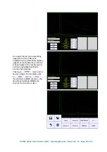
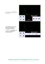
Case 3

 represents scanning above 

curved wall surface 
circumferentially – the wall 
thickness and pipe outside 
diameter should be keyed in to 
obtain actual 

t(A)

 , 

t(B) 

reading  


Summary of Contents for ISONIC utPod

Page 1: ... is si io on n 1 1 1 18 8 S So on no ot tr ro on n N ND DT T I IS SO ON NI IC C u ut tP Po od d U Ul lt tr ra a P Po or rt ta ab bl le e M Mu ul lt ti i P Pu ur rp po os se e U Ul lt tr ra as so on ni ic c T Te es st ti in ng g I In ns st tr ru um me en nt t ...

Page 2: ...ISONIC utPod from Sonotron NDT Operating Manual Revision 1 18 Page 2 of 94 ...

Page 3: ...without notice No part of this document may be reproduced or transmitted in any form or by any means electronic or mechanical for any purpose without the express written permission of Sonotron NDT 4 Pekeris st Rabin Science Park Rehovot Israel 76702 Covered by the United States patent 6545681 other US foreign patents pending ...

Page 4: ... 68 EEC Council Directive 73 23 EEC Low Voltage Directive as amended by Council Directive 93 68 EEC We Sonotron NDT Ltd 4 Pekeris Street Rehovot 76702 Israel certify that the product described is in conformity with the Directives 73 23 EEC and 89 336 EEC as amended ISONIC utPod Ultra Portable Multi Purpose Ultrasonic Testing Instrument The product identified above complies with the requirements of...

Page 5: ...3 23 EEC Low Voltage Directive as amended by Council Directive 93 68 EEC We Sonotron NDT Ltd 4 Pekeris Street Rehovot 76702 Israel certify that the product described is in conformity with the Directives 73 23 EEC and 89 336 EEC as amended ISONIC utPod LF Ultra Portable Multi Purpose Ultrasonic Testing Instrument Adapted for Low Frequency Ultrasound Applications The product identified above complie...

Page 6: ...ative or distributor provided the defective unit is returned properly packed with all transportation charges prepaid Any and all equipment replacement will be at the sole discretion of Sonotron NDT This warranty shall not apply to equipment subjected to misuse or abuse improper installation alteration neglect or accident This warranty is limited to the original purchaser and is not transferable No...

Page 7: ... ALARM 31 5 6 1 Switch Alarm ON OFF 31 5 6 2 Alarm Logic 31 5 6 3 Alarm Example 32 5 7 SUB MENU DAC 33 5 7 1 Theoretical DAC dB mm dB in 33 5 7 2 Experimental DAC recording signals from variously located reflectors 34 5 7 3 DGS 37 5 7 4 Multi Curve DAC DGS 39 5 7 5 DAC Mode 40 5 8 SUB MENU MEASURE 41 5 8 1 Probe Delay Incidence Angle 41 5 8 2 X Value 41 5 8 3 Link Display Delay and Probe Delay Set...

Page 8: ...Y 73 7 2 5 Submenu GATE A 73 7 2 6 Min Max 73 7 2 7 Data Logger 73 7 3 MEASUREMENT 74 7 3 1 Pure Digital Combined Thickness Display 74 7 3 2 Min Max 74 7 3 3 Data Logger 74 7 4 ZOOM A SCAN 74 8 ISONIC UTPOD FOR PC SW PACKAGE 75 8 1 ISONIC UTPOD CONNECTION TO COMPUTER 75 8 2 ISONIC UTPOD INSTRUMENT CONTROL 75 9 MISCELLANEOUS 76 9 1 SETTINGS 76 9 2 ISONIC UTPOD VIEWER 76 9 3 ISONIC UTPOD FIRMWARE UP...

Page 9: ...C utPod LF is a modified version of ISONIC utPod adopted for the low frequency ultrasound applications Comparing to ISONIC utPod it is characterized by the different frequency band and limits for settling the duration of the initial pulse refer to the Chapter 2 of present Operating Manual ISONIC utPod ADL and ISONUC utPod LF ADL are the models additonally featured with the continous automatic data...

Page 10: ...tudes from variously distanced equal reflectors up to 40 points 46 dB Dynamic Range Slope 120 dB s Available for Rectified and RF Display DGS Standard Library for 18 probes expandable Gates 2 Independent Gates Gate Start and Width Controllable over the whole range of A Scan time base settings in 0 1 mm 0 001 resolution Gate Threshold 5 95 of A Scan height controllable in 1 resolution Signal Evalua...

Page 11: ... on the thickness of paint coating layer Far Side Wall Thickness Measurement in tubes with use of regular single element probes Switchable into the simplest corrosion gauge mode digial readout only Comprehensive Data Logger Supervisor lock unlock function Full USB Controllability ISONIC utPod for PC SW package SW 808012 on the backup USB key USB Connection to PC with live large high quality A Scan...

Page 12: ...Thickness Measurement with use of regular single element probes no limit on the thickness of paint coating layer Far Side Wall Thickness Measurement in tubes with use of regular single element probes Switchable into the simplest corrosion gauge mode digial readout only Comprehensive Data Logger Supervisor lock unlock function Full USB Controllability ISONIC utPod for PC SW package SW 808012 on the...

Page 13: ...Thickness Measurement in tubes with use of regular single element probes Switchable into the simplest corrosion gauge mode digial readout only Comprehensive Data Logger Automatic Real Time Logger Docking Terminal for Integration into Autonomous Automatic Inspection System Supervisor lock unlock function Full USB Controllability ISONIC utPod for PC SW package SW 808012 on the backup USB key USB Con...

Page 14: ...lar single element probes no limit on the thickness of paint coating layer Far Side Wall Thickness Measurement in tubes with use of regular single element probes Switcheable into the simplest corrosion gauge mode digial readout only Comprehensive Data Logger Automatic Real Time Logger Docking Terminal for Integration into Autonomous Automatic Inspection System Supervisor lock unlock function Full ...

Page 15: ...eck Adaptor S 808042 Optional Item 5 Arm Fixture for instrument usage in the field S 808044 Optional Item 6 Soft case for ISONIC utPod S 808046 Optional Item 7 Ultrasonic probes fixtures scanners cables and other accessories depending on the inspection tasks to be resolved Optional Items Ultrasonic probes fixtures scanners cables and other accessories from any manufacturer may be used ...

Page 16: ...nual will be to give instructions in the basic set up and functional operation of ISONIC utPod Such information is covered in detail within the manual Other variable factors some of which are noted below and the actions necessary to control them are the responsibility of the user Details regarding these factors are beyond the scope of the operating manual 4 1 2 Training The adequate training of th...

Page 17: ...Revision 1 18 Page 17 of 94 4 2 ISONIC utPod Controls and Terminals DC Charger Input for Internal Battery Battery Charge Status LED RED charging GREEN full Sun Readable qVGA Touch Screen Power Switch Button USB Port Probe Terminal 2 Probe Terminal 1 ...

Page 18: ...it until ISONIC utPod start screen appears upon boot up completed Click on to operate ISONIC utPod as flaw detector refer to chapter 5 of the operating manual Click on to operate ISONIC utPod as thickness gauge using single element probes refer to chapter 6 of the operating manual Click on to operate ISONIC utPod as corrosion gauge using dual element probes refer to chapter 7 of the operating manu...

Page 19: ...erial select the dialogue language calibrate touch screen switching built in buzzer ON or OFF setting power saving sleep mode parameters identifying version release number of the currently installed firmware Refer to Chapter 9 of present Operating Manual To turn ISONIC utPod off click on or press power switch button during few seconds ...

Page 20: ...ion results and calibration set into a file Click on to upload A Scan accompanied with signal evaluation results and calibration set from a file Click on to freeze return to live A Scan Click on to return to upper level menu Current settings of flaw detector will be kept as default then 5 2 Submenu BASICS Click on in the Top Level Screen to enter the screen as below appears ...

Page 21: ...rrent Gain setting Touch area A on the A Scan the current Gain setting appears in that area upon and kept on the top of the screen for several seconds after area A untouched Touch area B on the screen and keep the said area touched unit Gain decreased to the needful value the appropriate indication is provided in the area A on the A Scan during all time of such Gain manipulation and kept on the to...

Page 22: ...ocity is below 5 2 3 Reject Click on to manipulate Reject setting Reject may be applied to rectified signals only Rectification Full NegHalf PosHalf refer to paragraph 5 4 3 of this Operating Manual Signals below Reject level small signals are suppressed Signals exceeding Reject level large signals are presented on the A Scan without affecting their original height while part of large signal below...

Page 23: ... echoes from reflectors with known material travel distance the Range and Display Delay settings to provide appearance of both echoes on the A Scan Ob completion click on to enter to screen allowing automatic calibration of ultrasonic velocity US Velocity and Probe Delay Click on and cover first echo by the Gate A refer to paragraph 5 5 3 of present Operating Manual ...

Page 24: ...Gate B refer to paragraph 5 5 3 of present Operating Manual Click on and key in material travel distance for the first echo then click on and key in material travel distance for the second echo On completion click on the values of Probe Delay and US Velocity will be defined by instrument automatically and indicated ...

Page 25: ...le element probe to be connected to Probe Terminal 2 refer to paragraph 4 2 of the operating manual Emitting crystal of dual element probe or emitting single element probe to be connected to Probe Terminal 1 refer to paragraph 4 2 of the operating manual Receiving crystal of dual element probe or receiving single element probe to be connected to Probe Terminal 2 refer to paragraph 4 2 of the opera...

Page 26: ...r initial pulse is recommended for most applications Pulse Width is tunable between 50 ns to 600 ns in 10 ns steps Pulse Width Firing Level of positive and negative half wave of the bipolar initial pulse are varying synchronously There are 12 grades 1 through 12 for setting Firing Level Unipolar Initial Pulse Pulse Width Firing Level Bipolar Initial Pulse Firing Level Firing Level Pulse Width Puls...

Page 27: ... Emitting crystal of dual element probe or emitting single element probe to be connected to Probe Terminal 1 refer to paragraph 4 2 of the operating manual Receiving crystal of dual element probe or receiving single element probe to be connected to Probe Terminal 1 refer to paragraph 4 2 of the operating manual 5 4 2 Filter Click on to control Filter settings Digital Filter may be switched ON OFF ...

Page 28: ...anual Revision 1 18 Page 28 of 94 5 4 3 Rectification Click on there are four rectification modes possible Rectification modes RF not rectified PosHalf positive half wave rectified NegHalf negative half wave rectified Full both waves rectified ...

Page 29: ...Click on in the Top Level Screen to enter the screen as below appears While used as flaw detector ISONIC utPod provides 2 independently controllable gates A and B 5 5 1 Switch Gate ON OFF To switch gate ON OFF touch the appropriate button Gate A is ON Gate A is OFF Gate B is ON Gate B is OFF Gate A Gate B ...

Page 30: ... the surface of the material which is determined through keying in Probe Delay 5 5 3 Draw Gate Click on or identical button for the Gate B then draw Gate A or Gate B in the new desired position on the A Scan This way allows redefining all three parameters of the gate quickly Refer also to the movie at http www sonotronndt com PDF OM_utPod MOV utPod_Draw_Gate MOV Initial Pulse Display Delay Time Ba...

Page 31: ...evel Screen to enter the screen as below appears 5 6 1 Switch Alarm ON OFF To switch Alarm for Gate A Gate B ON OFF touch the appropriate button either then provide the desired setting 5 6 2 Alarm Logic To setup Alarm Logic for Gate A Gate B ON OFF touch the appropriate button either then provide the desired setting ...

Page 32: ...gic setting for Gate A is Positive Alarm Indicator for Gate A is active the audible alarm is generated as well There is an echo matching with Gate B and not exceeding its threshold the Alarm Logic setting for Gate B is Negative Alarm Indicator for the Gate B is active the audible alarm is generated as well Gate A Gate B Alarm Indicator for Gate A Alarm Indicator for Gate B ...

Page 33: ...AC represents pure exponential law for distance amplitude curve said law is determined by dB mm dB in factor and value of Probe Delay refer to paragraph 5 7 1 of the operating manual at zero material travel distance surface theoretical DAC starts at 100 of A Scan height To enter dB mm dB in factor touch button then provide the desired setting To negate theoretical DAC touch then reduce dB mm dB in...

Page 34: ...ick on the Draw Gate mode Draw A is active so it is possible to manipulate Gate A over the entire A Scan area Recording 1st DAC echo Place probe onto DAC calibration block and maximize echo from the reflector closest to the probe first echo then place Gate A over received signal and capture first DAC echo through click on This leads to the recording of the first DAC echo the total number of stored...

Page 35: ...of 94 Recording 2nd DAC echo Place probe onto DAC calibration block and maximize echo from the reflector closest to the probe first echo then place Gate A over received signal and capture second DAC echo through click on This leads to the recording of the second DAC echo ...

Page 36: ...lick on This leads to the recording of the third DAC echo Refer also to the movie at http www sonotronndt com PDF OM_utPod MOV utPod_Creating_a_DAC MOV The highest echo in the Gate A will be stored said echo may either exceed Gate A threshold level or not Recorded echoes should be higher than 5 and lower than 100 of A Scan height Gain manipulation is allowed whilst creating modifying a DAC A total...

Page 37: ... blue line represents dependence of the back echo amplitude on the metal travel distance white line represents dependence of the FBH echo amplitude on the metal travel distance One of two reference blocks may be used to setup DGS back echo block inclined according to the probe angle incidence angle standard block either K1 IIW 1 or K2 IIW 2 the type of reference block and reflector are defined in ...

Page 38: ...amplitude on the metal travel distance appears at the standard level 80 of A Scan height for the maximal point and the required Gain setting is provided automatically Clicking on returns to the keying in stage On completion click on then on this will return to DAC submenu The file with just calibrated DGS to be stored in the instrument upon ...

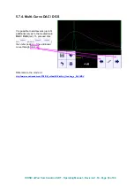
Page 39: ...lti Curve DAC DGS It is possible to add several up to 3 additional curves to the created main DAC DGS red To proceed click on or on then refer position of the additional curve through click on Refer also to the movie at http www sonotronndt com PDF OM_utPod MOV utPod_Creating_a_DAC MOV ...

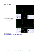
Page 40: ... Revision 1 18 Page 40 of 94 5 7 5 DAC Mode Since DAC DGS is created it is possible to setup appropriate mode of operation either DAC TCG or OFF after clicking on Refer also to the movie at http www sonotronndt com PDF OM_utPod MOV utPod_DAC_TCG MOV ...

Page 41: ...creen to enter the screen as below appears At least one gate either Gate A or Gate B should be active to proceed with measurements 5 8 1 Probe Delay Incidence Angle To key in Probe Delay Incidence Angle X Value click on then provide necessary setting 5 8 2 X Value To key in X Value for angle beam probe click on then click on ...

Page 42: ...ISONIC utPod from Sonotron NDT Operating Manual Revision 1 18 Page 42 of 94 Provide necessary setting and click on then To negate last setting change click on ...

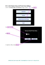
Page 43: ...ing Manual Revision 1 18 Page 43 of 94 5 8 3 Link Display Delay and Probe Delay Settings To link unlink Display Delay and Probe Delay settings or click on then click on Then check uncheck and click on To negate last setting change click on ...

Page 44: ... Gate A s A T A US Velocity s B Material Travel Distance mm or in of an echo matching with Gate B s B T B US Velocity a A Projection Distance mm or in of reflector returning an echo matching with Gate A measured respectfully front surface of angle beam probe a A s A sin Angle X Value a B Projection Distance mm or in of reflector returning an echo matching with Gate A measured respectfully front su...

Page 45: ...mandatory settings to be provided active theoretical DAC of 0 079 dB mm 2 dB in theoretical DAC refer to the paragraph 5 7 1 of the operating manual active Gate A Meas Mode Top refer to the paragraph 5 8 5 of the operating manual USVelocity Probe Delay Angle equal to actual values Gate A ON Gain setup to provide reference signal amplitude of 63 of the A Scan height It is also recommended but not m...

Page 46: ... For the ISONIC utPod firmware revision 1 35 and later there additional controls available in the digital readout field Click on allows reading of all measurements related to either Gate A or Gate B or as simultaneously selectable through click on To return to single value digital readout click on again or on ...

Page 47: ...ge 47 of 94 5 8 6 Flank and Top Click on then select the required mode either Top or Flank Meas Mode setting A Scan Flank T A T B s A s B t A t B a A a B T s t a V A V B H A H B V VC A VC B AWS Top T A T B s A s B t A t B a A a B T s t a V A V B H A H B V VC A VC B ...

Page 48: ...orrected depending on material thickness and curvature of the object being tested To provide necessary correction then click on Case 1 represents simplest scheme supposing that scanning is performed above semi infinite objects whereas coordinates t A t B are determined in accordance with the appropriate sketches equations and A Scans shown in paragraph 5 8 3 of the operating manual ...

Page 49: ...onotron NDT Operating Manual Revision 1 18 Page 49 of 94 Case 2 represents scanning above plate or scanning above tubular object longitudinally thickness of the material should be keyed in to obtain actual t A t B reading ...

Page 50: ...otron NDT Operating Manual Revision 1 18 Page 50 of 94 Case 3 represents scanning above curved wall surface circumferentially the wall thickness and pipe outside diameter should be keyed in to obtain actual t A t B reading ...

Page 51: ...above solid cylindrical object circumferentially or above spherical object For such case the diameter of the object being should keyed in and the thickness to be defined as Thickness 0 5 Diameter On completion new geometry correction settings click on To negate last geometry correction settings click on ...

Page 52: ...r right corner of the screen Clicking on enters into Freeze Peak mode allowing capturing of the signal peak envelope Indicator displays that Freeze peak mode is active On completing capturing signal peak envelope click on The color of the said indicator changes upon meaning that further capturing of the envelop is not possible Locked Peak Envelop mode To return to Freeze Peak mode click on Top ret...

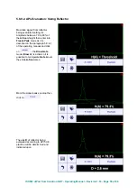
Page 53: ... into Freeze Peak mode as it is described in the paragraph 5 8 6 1 of the operating manual and click on the Draw Gate mode Draw A is active so it is possible to manipulate Gate A over the entire A Scan area Mark the signal peak envelop then click on the capture of that button indicates k factor found for the earlier used reference reflector according to API practice 5UE Click on to activate contro...

Page 54: ...perating Manual Revision 1 18 Page 54 of 94 Key in Dr then click on and on This will redefine k factor for the new reference reflector and indicate it correspondingly It is possible now to return to live A Scan and continue inspection ...

Page 55: ...0 to 90 of the A Scan height then enter into Freeze Peak mode as it is described in the paragraph 5 8 6 1 of the operating manual and click on the Draw Gate mode Draw A is active so it is possible to manipulate Gate A over the entire A Scan area Mark the signal peak envelop then click on The size D of reflector being evaluated according to API 5UE practice will be determined and indicated upon ...

Page 56: ...vision 1 18 Page 56 of 94 5 9 Zoom A Scan Double click on the A Scan expands it to the full screen area returns back to the combined A Scan Controls mode Refer also to the movie at http www sonotronndt com PDF OM_utPod MOV utPod_A Scan_Full_Screen MOV ...

Page 57: ...play Delay calibration stage it may occur the situation when it is necessary to observe completely an echo situated at the end of the A Scan field In such case enter to submenu BASICS then double click inside the designated area This will increase current Range setting by 10 To return double click in the designated area or click on any button ...

Page 58: ...rts Any non uniformity of USVelocity in the test material may result in erroneous thickness measurements USVelocity is affected to varying degrees by the temperature of the material being tested USVelocity changes due to temperature variation may affect the material being inspected and probe as well When temperature variables are expected frequent checks must be made to maintain instrument calibra...

Page 59: ...he leading edge of the first delay line echo has no meaning For each new measurement the instrument defines the accumulated probe and contact media delay automatically Material thickness D is determined then automatically through measurement of multiple material back echoes following first delay line echo Probe without delay line Gate A should be placed over at least two material back echoes at th...

Page 60: ...ximal one within the Gate A Pulse Width Firing Level Shape settings defined through submenu PULSER also have the influence on the measurement results and should be calibrated along with Gain USVelocity To be equal to the ultrasound velocity in the material To be equal to the ultrasound velocity in the material Refer also to paragraph 6 2 2 2 of the operating manual Reject This setting has no influ...

Page 61: ...k echoes then provide gating Gate A according to paragraph 6 2 1 of the operating manual then click on the screen as below appears Key in the Thickness of the material on which calibration is performed The corresponding USVelocity value is defined and displayed automatically Click on to use automatically found USVelocity value as default as a result the precise material thickness result is display...

Page 62: ...screen as below appears Pulser is permanently setup to Single while in the Thickness Gauge mode to control other parameters refer to paragraphs 5 3 2 5 3 3 and 6 2 2 1 of the operating manual 6 2 4 Submenu RECTIFY Click on in the Top Level Screen to enter the screen as below appears Refer to paragraphs 5 4 3 and 6 2 2 1 of the operating manual ...

Page 63: ...for other settings refer to paragraphs 5 5 2 5 5 3 and 6 2 1 of the operating manual 6 2 6 Min Max This function allows finding minimal maximal thickness for the series of thickness measurements performed either through point by point placement of the probe onto or scanning over material click on to proceed the screen as below appears Click on to begin a series scanning then perform thickness gaug...

Page 64: ...values among measured are indicated 6 2 7 Data Logger 6 2 7 1 Defining Format of the Data Logger In the ISONIC utPod Start Screen refer to paragraph 4 3 of the operating manual click on Click on the format selected for the data logger files for Thickness Gauge and or Corrosion Gauge then click on To negate the last data logger format changes click on ...

Page 65: ...lue through clicking on either or It should be noted that in order to accelerate the access to the selected cell every digit composing numerical value may be accessed directly through clicking on it the selected digit is highlighted To store single point measurement into the cell click on Free cell is represented by the following save open controls Cell already filled with single point measurement...

Page 66: ...vision 1 18 Page 66 of 94 6 2 7 4 Emptying Data Logger Memory With reference to paragraph 6 7 2 1 select any new format for the data logger differing from the currently active then click on On completion return to the desired format and click on again ...

Page 67: ...rther calibrations possible 6 3 1 Pure Digital Combined Thickness Display Click on to switch to pure digital combined A Scan Digital thickness display 6 3 2 Min Max Refer to paragraph 6 2 6 of the operating manual 6 3 3 Data Logger Refer to paragraph 6 2 7 of the operating manual 6 4 Zoom A Scan Refer to paragraph 5 9 of the operating manual ...

Page 68: ...rt or batch of parts Any non uniformity of USVelocity in the test material may result in erroneous thickness measurements USVelocity is affected to varying degrees by the temperature of the material being tested USVelocity changes due to temperature variation may affect the material being inspected and probe as well When temperature variables are expected frequent checks must be made to maintain i...

Page 69: ...ntered automatically refer to paragraph 7 2 2 2 of the operating manual Multiecho Material thickness D is determined through measurement of multiple back echoes whilst Gate A covers at least two of them The maximal back echo among the designated should be raised to at least 80 100 of the A Scan height It is also necessary that at least one back echo to follow the maximal one within the Gate A Mult...

Page 70: ...the Gate A Pulse Width Firing Level Shape settings defined through submenu PULSER also have the influence on the measurement results and should be calibrated along with Gain USVelocity To be equal to the ultrasound velocity in the material To be equal to the ultrasound velocity in the material Refer also to paragraph 7 2 2 2 of the operating manual Reject This setting has no influence on the measu...

Page 71: ...eiving of several back echoes then provide gating Gate A according to paragraph 6 2 1 of the operating manual then click on the screen as below appears Key in the Thickness of the material on which calibration is performed Click on upon completed Click on to use automatically determined USVelocity and Probe Delay value as default Multiecho Refer to paragraph 6 2 2 2 of the operating manual ...

Page 72: ...ss result is displayed To return to the upper screen click on 7 2 3 Submenu PULSER Click on in the Top Level Screen to enter the screen as below appears Pulser is permanently setup to Dual while in the Corrosion Gauge mode to control other parameters refer to paragraphs 5 3 2 5 3 3 and 7 2 2 1 of the operating manual ...

Page 73: ...phs 5 4 3 and 7 2 2 1 of the operating manual 7 2 5 Submenu GATE A Click on in the Top Level Screen to enter the screen as below appears Gate A is permanently switched ON for other settings refer to paragraphs 5 5 2 5 5 3 and 7 2 1 of the operating manual 7 2 6 Min Max Refer to paragraph 6 2 6 of the operating manual 7 2 7 Data Logger Refer to paragraph 6 2 7 of the operating manual ...

Page 74: ...rther calibrations possible 7 3 1 Pure Digital Combined Thickness Display Click on to switch to pure digital combined A Scan Digital thickness display 7 3 2 Min Max Refer to paragraph 6 2 6 of the operating manual 7 3 3 Data Logger Refer to paragraph 6 2 7 of the operating manual 7 4 Zoom A Scan Refer to paragraph 5 9 of the operating manual ...

Page 75: ...ONIC utPod for PC software 8 2 ISONIC utPod Instrument Control ISONIC utPod for PC software allows full control of the instrument through the Instrument Like Operating Surface as it is described in the chapters 4 through 7 of the present operating manual While connected to computer ISONIC utPod it is fully controllable with use of mouse and keyboard the live A Scan and readings are reproduced on t...

Page 76: ...oftware allows viewing of files captured by ISONIC utPod instruments in the PC and creating inspection reports in the forms of hard copy or editable format PDF DOC etc depending on standard software such as MS Office PDF Writer etc installed in the computer Data logger data may be previewed upon exported from ISONIC utPod to PC For each data logger cell thickness reading is presented along with co...

Page 77: ...tall ISONIC utPod for PC software package and to run it establishing USB communication between computer and the instrument at least once Otherwise ISONIC utPod Firmware Updater will not be able to operate Prior to starting ISONIC utPod Firmware Updater Switch on the computer Ensure that internal battery ISONIC utPod is fully charged or connect ISONIC utPod to external charger which plugged into th...

Page 78: ...start the update process the sequence of following screens appears during the automatic process just wait and do not disconnect the instrument from the computrer On receiving last screen click on then on the update is completed The attempt to run update on the ISONIC utPod with the up to date firmware on board will result appearance of the following screen Just click on on then on then ...

Page 79: ...notron NDT Operating Manual Revision 1 18 Page 79 of 94 9 4 Touch Screen Calibration In the ISONIC utPod Start Screen refer to paragraph 4 3 of the operating manual click on then click on touch the center touch the center ...

Page 80: ...ISONIC utPod from Sonotron NDT Operating Manual Revision 1 18 Page 80 of 94 Draw something on the screen to test the accuracy then click on Next touching of the screen will return to the Settings menu ...

Page 81: ... Sonotron NDT Operating Manual Revision 1 18 Page 81 of 94 9 5 Built In Buzzer ON OFF In the ISONIC utPod Start Screen refer to paragraph 4 3 of the operating manual click on then click on then check the desired option ...

Page 82: ... Sonotron NDT Operating Manual Revision 1 18 Page 82 of 94 9 6 Blank Screen Sleep Mode In the ISONIC utPod Start Screen refer to paragraph 4 3 of the operating manual click on then click on then check the desired option ...

Page 83: ...7 2013 or later ISONIC utPod for PC Software version 2 8 date of release Dec 16 2013 or later 10 2 Docking Terminal Comparing to regular ISONIC utPod unit the instruments equipped with the Real Time Logger option are featured with the Docking Terminal instead of DC Charger input Docking terminal allows keeping the instrument encapsulated into some device for example PIG Pipe Inspection Gauge robot...

Page 84: ...T gates or by other means to prevent damage to the utPod in case of failure The 9V voltage source ground should be connected to pin 7 through a ferrite bead to reduce possible noise Pins 6 9 conduct the USB connectivity and should be connected to a shielded cable using a twisted pair for pins 8 and 9 ISONIC utPod instruments equipped with the Real Time Logger are supplied with the modified externa...

Page 85: ...ISONIC utPod from Sonotron NDT Operating Manual Revision 1 18 Page 85 of 94 Reference connectivity design is shown below ...

Page 86: ...ion 1 18 Page 86 of 94 10 3 Operating Real Time Logger 10 3 1 Calibration Switch the instrument ON and connect to the computer using its USB cable or Docking Terminal Cable In the computer start ISONIC utPod for PC software upon software started click on ...

Page 87: ...ation of the first and second back wall echoes or interface echo and first back wall echo within entire predicted range of their variations It is recommended to bring the second back wall echo to 50 80 level of FSH Activate Gate A and set it up to cover the entire time slot for the appearance of the first and second back wall echo or interface echo and first back wall echo within entire predicted ...

Page 88: ...ISONIC utPod from Sonotron NDT Operating Manual Revision 1 18 Page 88 of 94 On completing calibration click on Then click on ...

Page 89: ...anual Revision 1 18 Page 89 of 94 10 3 2 New Real Time Log Record The Real Time Logger Screen appears ISONIC utPod may hold up to 30 Real Time Log records To activate new log click on then enter the name description of the new log and click on ...

Page 90: ...all echo counted from the first back wall echo or delay of the back wall echo counted from the interface echo T A The measurement results are recorded into the new log 10 3 2 2 Interrupt Logging Until it Started Click on any button except in the ISONIC utPod for PC start screen the confirm in the appeared dialogue box 10 3 2 3 Finish Logging The logging continues until one of the following occurs ...

Page 91: ...10 3 2 of this Operating Manual 10 3 4 Delete Existing Log Record Select the log record to overwrite then click on 10 3 5 Download Log Record into Computer Select the log record to overwrite then click on The log may have very large size so allow time for downloading them If for any reason ISONIC utPod disconnects from PC during the download the download will be resumed from the point where it was...

Page 92: ...ill be created It may be open using various MS Office and other software for example MS Excel and processed accordingly The data is sorted into 3 columns Column A record Column B T A as defined in the paragraph 10 3 2 1 of this Operating Manual in s Column C T A as defined in the paragraph 10 3 2 1 of this Operating Manual in s No Signal record means there were no reading taken due to absence of t...

Page 93: ...ISONIC utPod from Sonotron NDT Operating Manual Revision 1 18 Page 93 of 94 ...

Page 94: ...ISONIC utPod from Sonotron NDT Operating Manual Revision 1 18 Page 94 of 94 Harsh Inspection Site ISONIC utPod www sonotronndt com ...

Reviews: