


5
Chapter 3 – PCIe Card Installation and Chassis Setup Steps
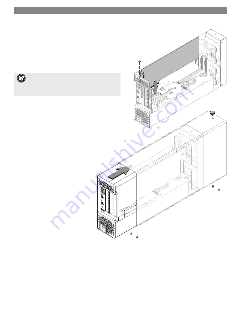
10.
Remove a PCIe card from its packaging, handling the card by its edges
and without touching any components or gold connector pins.
11.
Line up the card’s connector with the slot, and then gently but firmly
press the card straight into the slot;
do not rock the card or force the
card into the slot
. If you encounter excessive resistance, check the
card’s connector and the slot for damage, and then try inserting the
card again
(Figure 4)
.
12.
Repeat steps 10 and 11 as necessary with any remaining cards.
13.
If you installed a card which requires auxiliary power, connect the
auxiliary power connector to it now.
14.
If there are any unoccupied slots, install the PCIe slot covers you
removed previously
(Figure 4)
.
15.
Secure the cards and port access covers using the previously-removed
screws
(Figure 4)
.
16.
Grasping the enclosure, gently push the
module back inside from the rear as shown, and then secure
the enclosure to the bottom of the module using the four
screws you removed previously;
do not overtighten
the screws (Figure 5)
.
17.
Using the thumbscrew you removed previously,
secure the enclosure to the top of the module;
do not overtighten the screws (Figure 5)
.
Figure 4
Figure 5
Support Note:
If you are installing a x8 PCIe 1.1 card like the
original RED ROCKET (not RED ROCKET-X) or certain 10
Gigabit Ethernet cards, installing it into slot 2 may result in reduced
performance. We recommend you install it into either slot 1 or 3 for
best performance.


