


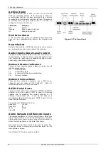


2. Net-Log Hardware
Archive Alarm
This red coloured LED is used to warn of loss of data
during a recording process. If the Net-Log is about to
overwrite data that has not been archived on to a remote
computer then this indicator will start to flash. The amount
of warning time you get before data is lost can be
configured in the main software.
LED State
Meaning
Off
Normal
Flashing
Data is about to be lost
On
Data has been lost
Disk Drive Alarm
A red coloured LED giving an indication that there has
been an error reading/writing from/to the internal hard
disk.
Reset Switch
Restarts the machine. NOTE that this does not overwrite
any configurations and simply reboots the machine.
Audio Inputs/Input Level Control
The audio inputs consist of four 3-pin XLR connectors (2-
channel stereo, 4-channel mono) with independent level
gain controls for each input, accessible through the rear-
panel using a flat-blade screwdriver.
Network Status Indicators
There are four network status indicators, which are all
labelled independently.
Rx Receiving
data.
Tx Transmitting
data.
Link
A network link has been established
Col Network
collision
Network Connections
There are two network connectors: one a BNC (coax,
10base2), and the other a RJ45 (10baseT). Either of
these can be used for TCP/IP connection.
RS232 Serial Ports
There are two 9 pin D-Type connectors (COM1 and COM2)
situated on the rear panel. COM1 is used for firmware
updates and for updating the network settings, i.e. IP
Address, Subnet Mask, etc. It can also be used as a
messaging output for data analysis. COM2 is used for the
Serial Control Interface.
The settings for COM1 are fixed at:-
Baud rate
115200
Data Bits
8
Parity
NONE
Stop Bits
1
Alarm Outputs And Remote Inputs
The remote connector is a 15 pin male D-type, which has
eight remote inputs to control recording and a double-
pole-double-throw alarm output relay which activates on
either the Archive Alarm or the Hard-Disk Alarm.
The inputs can be driven by 5V logic and are active low.
These can be set to momentary or latching action via the
main software screen.
See Chapter 12 for pin connection details.
Figure 2.2 The Rear Panel
Sonifex Net-Log User Handbook
12
Summary of Contents for Net-Log
Page 1: ...Sonifex Net Log User Handbook...
Page 6: ...Contents Sonifex Net Log User Handbook...
Page 10: ...License Form Sonifex Net Log User Handbook 4...
Page 16: ...1 Introduction Sonifex Net Log User Handbook 10...
Page 24: ...3 Net Log Set up Installation Sonifex Net Log User Handbook 18...
Page 32: ...5 Recording Sonifex Net Log User Handbook 26...
Page 36: ...6 Playing Downloading Sonifex Net Log Win User Handbook 18...
Page 48: ...9 Serial Control Interface Sonifex Net Log Win User Handbook 30...
Page 56: ...11 The Administrator Sonifex Net Log Win User Handbook 38...
Page 62: ...13 Technical Specification Sonifex Net Log Win User Handbook 44...
Page 64: ...14 Glossary Sonifex Net Log Win User Handbook 46...