Introduction & Installation Page 1-5
HY02 Digital TBU User's Guide
1.5. Using the HY02
Digital
1.5.1. Receiving a Call
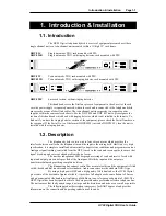
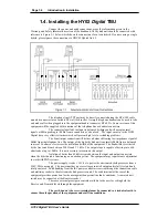
With the equipment connected as in Figure 1-1, calls may be received and detected
by the ringer in the telephone handset. To receive the call, lift the handset and establish contact with
the caller. The call may be diverted to the telephone hybrid by pressing either the local Line Connect
switch at the front panel or by means of the Remote Divert switch. The hybrid unit will now act as a 4
wire to 2 wire converter with a signal input at the Line Input and telephone signal output at the Line
Output. When the equipment is on, the On LED indicator will be illuminated and when an incoming
call is seized the Hold indicator will be illuminated.
The call may be cleared by re-pressing the Line Connect switch ( which can be
remoted ), or by means of the K-break provided in the equipment. Automatic line clearance is provided
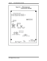
when the caller hangs up, if jumper JP2 is set ( default condition ).
If the DHY 02TR or DHY 02SR have been purchased, which contain the integrated
ringing detector, the call will be picked up automatically and passed to the telephone hybrid ( This will
happen if jumper JP3 has been set , which is the default configuration ). The ring number on which the
detector will pick the call up can be adjusted from 1 to 5 by altering RV3 ( Default value is 2 rings ).
With both auto-answer and auto-clearance in use, call handling can be completely
automatic in operation.
1.5.2. Making a Call
To initiate a call, lift the Handset and dial the required telephone number. When the
call has been established, press the Line Connect switch and the call will be handed over to the
telephone hybrid unit. To clear the line at the end of the call, press the Line Connect switch. The Line
Connect switch lamp is off in the non-connected mode and on in the connected mode.
Please note that any adjustments and settings should be carried out by
competent engineering personnel.
1.6. Front Panel Controls and Displays
1.6.1. LED Indicators
There are two LED indicators providing general information about the equipment :
A status LED, marked “On”, shows that the equipment is powered and operational.
A line hold LED indicates when the telephone line is seized and connected.
1.6.2. Bar Graph LED’s
Additionally there are independent LED bar graph displays of 10 elements each
showing the relative levels of both the received and transmitted signals. The presence of signals within
the normal zone up to the maximum level , before limiting takes place, is an indication of normal
operation. The 0dB level mark indicates the safe level for signal operation. The three red LED
indicators above this mark indicate headroom of +6dB above the 0dB level.
Signals sent to the line can be monitored at the Tx level bar graph and any
adjustments in level can be set by the Tx gain control preset. Signals received from the telephone line
can be monitored at the Rx level bargraph and the signal levels set by the Rx gain control preset. The
Tx and Rx levels must not exceed the maximum bar graph display, to prevent distortion and breakup.
The Rx and Tx bar graphs can be used to set the Rx and Tx gains using test tones and
a small flat-blade screw-driver.
Summary of Contents for HY02 DIGITAL
Page 14: ...Page 1 8 Introduction Installation HY02 Digital TBU User s Guide This page deliberately blank ...
Page 16: ...Page 2 2 Circuit Description Controls HY02 Digital TBU User s Guide ...
Page 22: ...Page 2 8 Circuit Description Controls HY02 Digital TBU User s Guide ...
Page 25: ...Page 0 Index HY02 Digital TBU User s Guide ...
Page 27: ...HY02 Digital TBU User s Guide ...


