Circuit Description & Controls Page 2-1
HY02 Digital TBU User's Guide
2. Circuit Description & Controls
The HY02
Digital
Telephone Hybrid consists of two parts separately enclosed for
safety within a 19” rack frame housing. The two parts are connected by linking cables at the rear of
rack frame. Isolation is achieved by means of the barriers created at the power supply and the hybrid
electronics.
2.1. Mains Power Unit Circuit Description
The mains power is available in either single or double configuration for use with
either one or two electronic hybrid units, within one rack frame assembly.
The 230V 50Hz mains connection is via an IEC fused connector type CEE22. The
230V supply generates low voltage a.c. through an isolation transformer(s) TR1 (TR2) the outputs of
which are smoothed and regulated to
±
15 d.c. by means of the electronic regulators Q1 and Q2 (Q3,
Q4)
±
15V connected to the electronic hybrid together with an earth bond and remote connections
through the power cable at the rear of the power supply.
The
±
15V d.c. output of the power is protected against high voltage breakdown by
d.c. fuses F1, F2 (F3, F4) and the voltage sensitive zener diodes D1, D2 and (D7, D8) in the twin
configuration.
A single overvoltage fault will cause overvoltage current to flow in D1 and D2 (D7,
D8) rupturing fuses F1, F2 (F3, F4) removing the overvoltage condition.
2.2. Electronic Digital Hybrid Unit Circuit
Description
The electronic digital hybrid unit comprises the following sections (see block
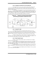
diagram, Figure 2-1 ).
2.2.1 Input circuits and limiter.
2.2.2 Telephone line barrier and transformer.
2.2.3 Output circuits.
2.2.4 Divert switch logic.
2.2.5 Line balancing electronics.
2.2.6 Ring detect circuits.
2.2.7 Dial tone detect circuits.
2.2.8 Displays
2.2.1. Input Circuits and Limiter
The line input connection at the XLR-3-31 is coupled directly to the line bridging
input transformer TR2. The input impedance is greater than 10K ohms balanced floating with a high
common mode rejection ratio. The input transformer is coupled to the limiter transistors Q24 and Q25
and amplifier Q3b via R50, C26, C27 and R52. The limiter output delivers full bandwidth signals
which drives the digital processor. Analogue signal limiting controlled from the DSP is used in the
send and receive paths to ensure that signal break-up and severe overload problems do not occur. The
telephone send circuit drives the line via a transformer/capacitor/divert relay combination. The receive
circuit uses an independent transformer coupled bridging circuit. This is connected to the send circuit
in two wire mode and to a separate input for four wire operation. An analogue sidetone cancellation
network is switched in if the board is ‘on-line’ and in two wire mode.
Summary of Contents for HY02 DIGITAL
Page 14: ...Page 1 8 Introduction Installation HY02 Digital TBU User s Guide This page deliberately blank ...
Page 16: ...Page 2 2 Circuit Description Controls HY02 Digital TBU User s Guide ...
Page 22: ...Page 2 8 Circuit Description Controls HY02 Digital TBU User s Guide ...
Page 25: ...Page 0 Index HY02 Digital TBU User s Guide ...
Page 27: ...HY02 Digital TBU User s Guide ...


