


Ⅲ
-IV-6
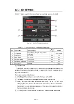
4-3
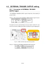
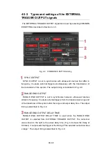
EXTERNAL TRIGGER OUTPUT setting
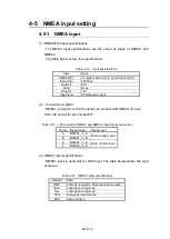
4-3-1
Connection of EXTERNAL TRIGGER
OUTPUT signal
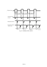
The EXTERNAL TRIGGER OUTPUT signal is output from J30 connector pin
number CC/DD.
Table 4-5
Table of J30 connector EXTERNAL TRIGGER OUTPUT signal connection
Pin No. Single Name
Single Level
CC
EXT_TRIG_out
Open collector output and
TTL level input
DD
GND
GND
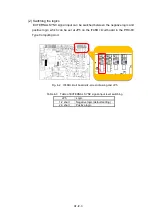
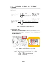
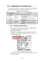
The signal level can be switched between the open collector and the TTL level.
It can be set at JP3 on IF46B circuit board in the PRC-63 Type Computing Unit.
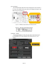
Fig. 4-5
IF46B circuit board silk-screen drawing and JP3
Table 4-6
Switching of the EXTERNAL TRIGGER OUTPUT signal levels
JP4
Logic
1-2 short
Negative logic (default setting)
2-3 short
Positive logic
Summary of Contents for KSE-310
Page 1: ...KSE 310 TYPE FISH SIZING ECHO SOUNDER Instruction Manual Ver 5 04E SONIC CORPORATION ...
Page 2: ... MEMO ...
Page 163: ...III 153 ...
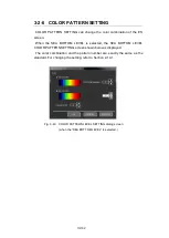
Page 166: ...III 156 3 2 1 CURSOR CONTROL This is described in Section 2 9 ...
Page 186: ...Ⅲ IV 14 Fig 4 13 NET DEPTH Display Method dialog ...
Page 196: ......


