5
Connections
G
e
tting
Sta
rted
Se
tu
p
Basi
c
Ope
rations
Ad
vanc
e
d
Fe
atures
He
lp
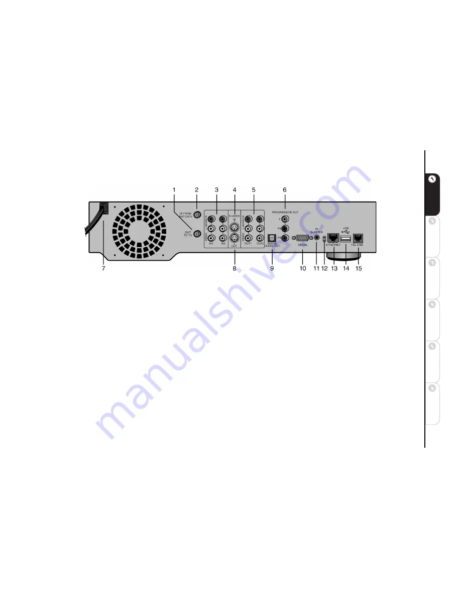
:: Rear Panel Overview
1 OUT TO TV
Connect to a television VHF/UHF jack with coaxial cable.
2 IN FROM ANT/CATV
Connect an antenna, cable TV coaxial cable, or cable box with coaxial cable.
3 VIDEO/AUDIO IN 1/IN 2
Connect to the Audio/Video outputs of a cable box or satellite receiver using standard audio/
video cables.
4 S-VIDEO IN
Connect to a cable box or satellite receiver that has S-Video Out. The Audio/Video IN 2 connectors must be
used with S-Video to receive sound. Please note that S-Video In is part of Line 2.
5 VIDEO/AUDIO OUT 1/OUT 2
Connect to the Audio/Video inputs of a television, monitor or A/V receiver using stan-
dard audio/video cables.
6 PROGRESSIVE OUT
Connect to a television, monitor or A/V receiver that has Progressive Video In.
7 POWER CORD
Connect to an electrical outlet.
8 S-VIDEO OUT
Connect to a television, monitor or A/V receiver that has S-Video In. Please note that Video Out 1, Video
Out 2 and S-Video are active at all times.
9 DIGITAL AUDIO OUT (OPTICAL)
Connect to an audio/video receiver equipped with an optical input.
10 SERIAL CONTROL
Connect to a satellite receiver that has a Serial port. This allows ReplayTV to change the channels on
the satellite receiver.
The IR Blaster is not needed if the satellite receiver has Serial Out
.
11 IR BLASTER
Connect and affix the IR emitter over the infrared detector on a cable box or satellite receiver. This allows
ReplayTV to change the channels on these devices.
12 NETWORK ACTIVITY AND LINK LIGHTS
Indicate the status of ReplayTV when using the Ethernet port. The green
light indicates that ReplayTV is connected to the network. The yellow light indicates network activity; i.e., data is being trans-
ferred to or from the unit.
Summary of Contents for ReplayTV 5000
Page 1: ...ReplayTV 5000 User s Guide...
Page 26: ...20 ReplayTV 5000...
Page 85: ......
Page 86: ...2841 Mission College Blvd Santa Clara CA 95054 1838...


