background image

CMP-400 – USER MANUAL 

37 

4.1.1  Sockets  


11 

measurement socket 

V/Ω/TEMP 

Measurement socket for the purpose of measurements of di-
rect  and  alternative  voltages  resistance,  frequency  and  tem-
perature. 

12 

measurement socket COM 

Measurement  socket  common  for  all  the  measurement  func-
tions  except  of  current  measurements  (connection  to  the 
mass of the device). 

4.1.2  Elements of selection of the measurement function 

 1  

current clamp


 2  

non-contact AC voltage indicator light


 3  

clamp trigger


 4  

rotational selector


Selection of function: 


OFF


– meter off, 


V

 – direct and alternative voltage measurement, 


Ω

  –  resistance  and  continuity  measurement  and 

diode testing, 


°F 

– Fahrenheit temperature measurement, 


°C 

– Celsius temperature measurement, 


4A~


– alternative current measurement up to 4A, 


40A~


– alternative current measurement up to 40A, 


400A~


– alternative current measurement up to 400A. 

 5  

HOLD button 


Data Hold function, 


Back Light function (after holding for 2s). 

 6  

REL button 


Relative measurement function, 


Exit of relative measurement  

 7  

LCD display 

 8  

MODE button 


Changing of measurement mode 

Summary of Contents for CMP-400

Page 1: ...INSTRUKCJA OBSŁUGI 1 USER MANUAL 28 MANUAL DE USO 55 CMP 400 v1 8 29 08 2019 ...

Page 2: ......

Page 3: ...1 INSTRUKCJA OBSŁUGI CĘGOWY MIERNIK PRĄDU ZMIENNEGO CMP 400 Wersja 1 8 29 08 2019 ...

Page 4: ...zych cech przyrządu CMP 400 należą automatyczna lub ręczna zmiana zakresów funkcja HOLD umożliwiająca odczyt pomiarów przy niedosta tecznym oświetleniu lub w trudno dostępnych miejscach funkcja REL umożliwiająca dokonywanie pomiarów względ nych sygnalizacja dźwiękowa ciągłości obwodu Beeper samoczynne wyłączanie nieużywanego przyrządu wyświetlacz 3 cyfry bezpieczne osłonięte szczęki pomiarowe wzmo...

Page 5: ...cz ciekłokrystaliczny LCD 11 4 3 Przewody 12 5 Pomiary 12 5 1 Pomiar prądu przemiennego 12 5 2 Pomiar napięcia 13 5 3 Pomiar rezystancji 14 5 4 Test ciągłości obwodu 14 5 5 Test diod 15 5 6 Pomiar częstotliwości lub cyklu roboczego 16 5 7 Pomiar temperatury 17 5 8 Bezdotykowy test napięcia 18 6 Funkcje specjalne 19 6 1 Ręczna zmiana podzakresów 19 6 2 Tryb pomiaru względnego 19 6 3 Funkcja HOLD i ...

Page 6: ...STRUKCJA OBSŁUGI 4 9 Czyszczenie i konserwacja 21 10 Magazynowanie 22 11 Rozbiórka i utylizacja 22 12 Załączniki 22 12 1 Dane techniczne 22 12 2 Wyposażenie standardowe 25 13 Serwis 25 14 Usługi laboratoryjne 26 ...

Page 7: ... opisują sytuacje w których może dojść do zagrożenia życia lub zdrowia jeżeli nie przestrzega się instrukcji Słowo UWAGA rozpoczyna opis sytuacji w której niezastoso wanie się do instrukcji grozi uszkodzeniem przyrządu Wskazania ewentualnych problemów są poprzedzane słowem Uwaga OSTRZEŻENIE Przed użyciem przyrządu należy dokładnie przeczytać niniej szą instrukcję i zastosować się do przepisów bezp...

Page 8: ...ży zachować dużą ostrożność przy pomiarze napięć prze kraczających 35VDC lub 25VAC RMS gdyż stanowią one po tencjalne zagrożenie porażeniem przy sprawdzaniu obecności napięcia należy upewnić się że funkcja ta działa prawidłowo za pomocą pomiaru znanej warto ści napięcia zanim przyjmie się że zerowy odczyt oznacza brak napięcia przed przystąpieniem do pomiarów należy ustawić przełącznik funkcji w o...

Page 9: ...ny serwis OSTRZEŻENIE Nigdy nie wolno przystępować do pomiarów jeżeli użytkow nik ma mokre lub wilgotne dłonie OSTRZEŻENIE Nie wolno dokonywać pomiarów w atmosferze grożącej wy buchem np w obecności gazów palnych oparów pyłów itp W przeciwnym razie używanie miernika w tych warun kach może wywołać iskrzenia i spowodować eksplozję UWAGA Wartości graniczne sygnału wejściowego Funkcja Maksymalna warto...

Page 10: ...cznych napięć Podwójna izolacja 3 Przygotowanie miernika do pracy Po zakupie miernika należy sprawdzić kompletność zawartości opakowania Przed przystąpieniem do wykonywania pomiarów należy upewnić się że stan baterii pozwoli na wykonanie pomiarów sprawdzić czy obudowa miernika i izolacja przewodów pomia rowych nie są uszkodzone dla zapewnienia jednoznaczności wyników pomiarów zaleca się do gniazda...

Page 11: ...CMP 400 INSTRUKCJA OBSŁUGI 9 4 Opis funkcjonalny 4 1 Gniazda pomiarowe i elementy wyboru funkcji pomiarowej Rys 1 CMP 400 Ω ...

Page 12: ...owego detektora napięcia 3 dźwignia cęgów 4 przełącznik obrotowy Wybór funkcji OFF miernik wyłączony V pomiar napięcia stałego lub przemiennego Ω pomiar rezystancji ciągłości i test diod F pomiar temperatury w stopniach Fahrenheita C pomiar temperatury w stopniach Celsjusza 4A pomiar prądu przemiennego do 4A 40A pomiar prądu przemiennego do 40A 400A pomiar prądu przemiennego do 400A 5 przycisk HOL...

Page 13: ...iekłokrystaliczny LCD Rys 2 Wyświetlacz ciekłokrystaliczny miernika CMP 400 znak minus DC AC napięcie prąd stałe zmienne AUTO symbol automatycznego wyboru podzakresu symbol włączenia testu diod symbol włączenia testu ciągłości HOLD symbol włączenia funkcji HOLD REL symbol włączenia funkcji pomiaru względnego Hz symbol włączenia trybu testu częstotliwości lub cyklu roboczego ...

Page 14: ...ewodów grozi porażeniem wysokim napięciem lub błędami pomiarowymi 5 Pomiary Należy dokładnie zapoznać się z treścią tego rozdziału ponie waż zostały w nim opisane sposoby wykonywania pomiarów i pod stawowe zasady interpretacji wyników 5 1 Pomiar prądu przemiennego OSTRZEŻENIE Nie należy dokonywać pomiarów w obwodach o nieznanym potencjale Nie wolno przekraczać maksymalnych wartości zakresów pomiar...

Page 15: ...zęki miernika są w pełni zaciśnięte W przeciwnym razie miernik nie będzie w stanie dokonać dokładnych pomiarów Najdo kładniejszy pomiar uzyskamy kiedy przewód będzie znaj dował się w centrum szczęk pomiarowych 5 2 Pomiar napięcia Aby wykonać pomiar napięcia należy ustawić przełącznik obrotowy w pozycji V za pomocą przycisku MODE TRYB wybrać napięcie AC lub DC w razie potrzeby przyciskiem RANGE ust...

Page 16: ...owy w pozycji Ω podłączyć czerwony przewód pomiarowy do gniazda V Ω TEMP a czarny do gniazda COM sprawdzić czy przy rozwartych przewodach wyświetlany jest wynik 0L a w przypadku zwartych końcówek sond pomiaro wych wynik 000 0 w razie potrzeby przyciskiem RANGE ustawić ręcznie zakres pomiarowy przyłożyć ostrza sond do punktów pomiarowych odczytać wynik pomiaru na wyświetlaczu po zakończeniu pomiaró...

Page 17: ... wynik 0L a w przypadku zwartych końcówek sond pomiaro wych wynik 000 0 któremu towarzyszy sygnał dźwiękowy przyłożyć ostrza sond do punktów pomiarowych odczytać wynik pomiaru na wyświetlaczu sygnał dźwiękowy pojawia się przy wartościach rezystancji poniżej ok 50 po zakończeniu pomiarów wyjąć przewody z gniazd pomiaro wych miernika 5 5 Test diod OSTRZEŻENIE Nie wolno dokonywać pomiarów w obwodzie ...

Page 18: ...rwa w ob wodzie na wyświetlaczu pojawi się odczyt 0L po zakończeniu pomiarów wyjąć przewody z gniazd pomiaro wych miernika 5 6 Pomiar częstotliwości lub cyklu robo czego OSTRZEŻENIE Nie wolno przystępować do pomiarów jeżeli przedział baterii jest otwarty Aby wykonać pomiar należy ustawić przełącznik obrotowy w pozycji V podłączyć czerwony przewód pomiarowy do gniazda V Ω TEMP a czarny do gniazda C...

Page 19: ...em termoelektrycznym została odłączona przed przejściem do innej funkcji pomiarowej Aby wykonać pomiar należy ustawić przełącznik obrotowy w pozycji C lub F podłączyć sondę temperatury do ujemnego gniazda COM oraz dodatniego gniazda V Ω TEMP przestrzegając biegunowości przyłożyć głowicę sondy temperatury do testowanego urządzenia Kontakt głowicy z mierzoną częścią testowanego urządzenia należy utr...

Page 20: ...od napięciem lub wypro wadzenia elektrycznego pod napięciem jeżeli obecne jest napięcie przemienne wówczas zapali się dioda sygnalizacyjna detektora Uwaga Przewody kabli elektrycznych są często skręcone Aby osiągnąć najlepsze rezultaty należy przesunąć czujnik wzdłuż kabla celem umieszczenia go w bliskim sąsiedztwie przewodu znajdującego się pod napięciem Uwaga Detektor jest wysoce czułym urządzen...

Page 21: ... go przez 2 sekundy aby wyjść z trybu ręcznego wyboru zakresu i powrócić do automatycznego wyboru zakresu 6 2 Tryb pomiaru względnego W celu uruchomienia trybu pomiaru względnego należy naci snąć przycisk REL pojawi się symbol REL na wyświetlaczu Na stępnie wyświetlany jest wynik jako wartość odniesienia przy pomia rze względnym np jeśli wartością odniesienia jest 24V a aktualnym odczytem jest war...

Page 22: ... diod ciągłość 7 Zanim oddasz miernik do serwisu Zanim prześlesz przyrząd do naprawy zadzwoń do serwisu być może okaże się że miernik nie jest uszkodzony a problem wystąpił z innego powodu Usuwanie uszkodzeń miernika może być przeprowadzane tylko w placówkach upoważnionych przez producenta Zalecane postępowanie w niektórych sytuacjach występujących podczas użytkowania miernika OBJAW PRZYCZYNA POST...

Page 23: ...STRZEŻENIE Pozostawienie przewodów w gniazdach podczas wymiany baterii może spowodować porażenie niebezpiecznym napię ciem Aby wymienić baterię należy wyjąć przewody z gniazd pomiarowych i przełącznik obrotowy ustawić w pozycji OFF odkręcić wkręt pokrywy baterii w górnej części obudowy zdjąć pokrywę baterii wyjąć rozładowaną baterię i włożyć nową założyć zdjętą pokrywę i przykręcić wkręt mocujący ...

Page 24: ...adami innego rodzaju Zużyty sprzęt elektroniczny należy przekazać do punktu zbiórki zgodnie z Ustawą o zużytym sprzęcie elektrycznym i elektronicz nym Przed przekazaniem sprzętu do punktu zbiórki nie należy sa modzielnie demontować żadnych części z tego sprzętu Należy przestrzegać lokalnych przepisów dotyczących wyrzu cania opakowań zużytych baterii i akumulatorów 12 Załączniki 12 1 Dane techniczn...

Page 25: ...stawowa 400 0mV 0 1mV 1 5 w m 30 cyfr 4 000V 0 001V 1 8 w m 8 cyfr 40 00V 0 01V 400 0V 0 1V 600V 1V 2 5 w m 8 cyfr zakres częstotliwości 50 400Hz Pomiar rezystancji Zakres Rozdzielczość Niepewność podstawowa 400 0 0 1 1 w m 4 cyfry 4 000k 0 001k 1 5 w m 2 cyfry 40 00k 0 01k 400 0k 0 1k 4 000M 0 001M 2 5 w m 3 cyfry 40 00M 0 01M 3 5 w m 5 cyfr Pomiar częstotliwości Zakres Niepewność podstawowa 10Hz...

Page 26: ... stopień zanieczyszczenia 2 d zasilanie miernika bateria 9V e rozmiar cęgów otwarcie ok 30mm 1 2 f test diody I 0 3mA U0 1 5V DC g test ciągłości I 0 5mA sygnał dźwiękowy dla R 50Ω h wskazanie przekroczenia zakresu symbol 0L i częstotliwość pomiarów 2 odczyty na sekundę j impedancja wejściowa 10MΩ V AC DC k wyświetlacz LCD wskazanie 4000 l wymiary 197 x 70 x 40 mm m masa miernika 183 g n temperatu...

Page 27: ...u temperatury typ K WASONTEMK adapter do sond temperatury typu K WAADATEMK futerał instrukcja obsługi karta gwarancyjna certyfikat kalibracji 13 Serwis Prowadzącym serwis gwarancyjny i pogwarancyjny jest SONEL S A ul Wokulskiego 11 58 100 Świdnica tel 74 858 38 00 Biuro Obsługi Klienta e mail bok sonel pl internet www sonel pl Uwaga Do prowadzenia napraw serwisowych upoważniony jest jedy nie SONEL...

Page 28: ...KTRYCZNYCH ORAZ PARAMETRÓW SIECI ENERGETYCZNYCH o mierniki napięcia o mierniki prądu w tym również mierniki cęgowe o mierniki rezystancji o mierniki rezystancji izolacji o mierniki rezystancji uziemień o mierniki impedancji pętli zwarcia o mierniki zabezpieczeń różnicowoprądowych o mierniki małych rezystancji o analizatory jakości zasilania o testery bezpieczeństwa sprzętu elektrycznego o liczniki...

Page 29: ...a odstępów czasu mię dzy wzorcowaniami przyrządów pomiarowych Firma SONEL S A zaleca dla produkowanych przez siebie przyrządów wykonywanie po twierdzenia metrologicznego nie rzadziej niż co 12 miesięcy Dla wprowadzanych do użytkowania fabrycznie nowych przyrządów posiadających Świadectwo Wzorcowania lub Certyfikat Kalibracji kolejne wykonanie potwierdzenia metrologicznego wzorcowanie zaleca się pr...

Page 30: ...28 USER MANUAL AC CLAMP METER CMP 400 Version 1 8 29 08 2019 ...

Page 31: ...automatic or manual regulation of the measurement range DATA HOLD function which facilitates readings of measure ments in the case of insufficient lighting or in inaccessible plac es ZERO function which allows you to make measurements rela tive to a stored reference value the function of automatic switching of the meter into the standby mode in order to prolong the durability of batteries circuit ...

Page 32: ...t leads 39 5 Measurements 39 5 1 AC current measurements 39 5 2 AC and DC voltage measurements 40 5 3 Resistance measurements 41 5 4 Continuity Measurements 42 5 5 Diode Measurements 42 5 6 Frequency or duty cycle measurements 43 5 7 Temperature measurements 44 5 8 Non Contact AC Voltage Measurements 45 6 Special functions 45 6 1 Manual range selection 45 6 2 Relative mode 46 6 3 DATA HOLD Functio...

Page 33: ...CMP 400 USER MANUAL 31 10 Storage 49 11 Dismantling and utilization 49 12 Attachments 49 12 1 Technical data 49 12 2 Standard equipment 52 13 Manufacturer 52 14 Laboratory services 53 ...

Page 34: ...dations presented in the present manual not be observed The word ATTENTION introduces a description of a situation where non observance of the recommendations presented in the present manual may imply damage for the meter Indications of possible problems are preceded by the word Attention WARNING Before using the instrument acquaint yourself with the pre sent manual and observe the safety regulati...

Page 35: ...who also must be trained regarding the industrial safety regulations Use great care when making measurements if the voltages are greater than 25V AC rms or 35V DC These voltages are consi dered a shock hazard Before use for non contact AC voltage measurements always test the voltage detector on a known live circuit to verify proper operation Set function switch to the appropriate position before m...

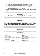
Page 36: ...s must be realised solely by an authorised service work shop WARNING Do not realise measurements with wet hands WARNING Do not realise measurements in environments in which there are inflammable gases Otherwise operation of the meter under such conditions may cause sparking and explosion ATTENTION Input Limits Function Maximum Input A AC 400A V DC V AC 600V DC AC Frequency Resistance Diode Continu...

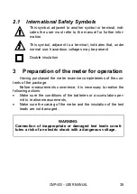
Page 37: ... Preparation of the meter for operation Having purchased the meter examine completeness of the con tents of the package Before measurements commence it is necessary to realise the following actions Make sure the conditions of the batteries or accumulators per mit to realise measurements Make sure the casing of the meter and the insulation of the test leads are not damaged WARNING Connection of ina...

Page 38: ...CMP 400 USER MANUAL 36 4 Functional description 4 1 Measurement sockets and elements of selection of the measurement function Illustration 1 CMP 400 Ω ...

Page 39: ...n contact AC voltage indicator light 3 clamp trigger 4 rotational selector Selection of function OFF meter off V direct and alternative voltage measurement Ω resistance and continuity measurement and diode testing F Fahrenheit temperature measurement C Celsius temperature measurement 4A alternative current measurement up to 4A 40A alternative current measurement up to 40A 400A alternative current ...

Page 40: ...y cover 4 2 LCD display Illustration 2 LCD display of the CMP 400 meter minus sign AC DC AC alternating current and DC direct currrent AUTO AutoRange mode diode test mode continuity check mode HOLD Data Hold mode ZERO Relative Measurement mode Hz frequency duty cycle test mode k M Ω m V C F A units of measure list ...

Page 41: ... measurement errors 5 Measurements It is recommended to get acquainted thoroughly with the con tents of the present chapter since it describes the measurement systems the manner of realisation of measurements and the basic principles of interpretation of the results 5 1 AC current measurements WARNING Do not take current readings on circuits where the maximum current potential is not known Do not ...

Page 42: ... sure the clamp is properly placed Otherwise the results of the measurements will not be exact The most exact result we will get if the wire is placed in the middle of clamp 5 2 AC and DC voltage measurements In order to realise a measurement of AC or DC voltage it is necessary to realise the following actions set the function switch to the V position select AC or DC with the MODE button with the ...

Page 43: ...the position Ω connect the red test lead to sockets V Ω TEMP and the black one to sockets COM make sure symbol is displayed with open test leads and in the case of shorted terminals of the measurement probes the display shows 0 with the RANGE button set the measurement range manually if necessary touch the test probe tips across the circuit or component under test it is best to disconnect one side...

Page 44: ...t lead to sockets V Ω TEMP and the black one to sockets COM press the MODE button until appears in the display make sure symbol is displayed with open test leads and in the case of shorted terminals of the measurement probes the display shows 0 touch the test probe tips to the circuit under test read the result of the measurement on the display if the re sistance is 50Ω a tone will sound having do...

Page 45: ...d devices will indicate near 0mV and an open device will indicate OL in both polarities having done the test disconnect the test leads from the meter 5 6 Frequency or duty cycle measure ments WARNING Do not realise measurements if the battery compartment is open In order to realise frequency or duty cycle measurement it is necessary to realise the following actions place the rotational selector in...

Page 46: ...emperature measurement it is necessary to realise the following actions place the rotational selector in the position C or F insert the temperature probe into the negative COM and the V Ω TEMP terminals making sure to observe the correct po larity touch the temperature probe head to the part whose tempera ture you wish to measure keep the probe touching the part under test until the reading stabil...

Page 47: ...ical cord sets are often twisted For best results rub the probe tip along a length of the cord to assure placing the tip in close proximity to the live conduc tor Note The detector is designed with high sensitivity Static electric ity or other sources of energy may randomly trip the sensor This is normal operation 6 Special functions 6 1 Manual range selection When the meter is first turned on it ...

Page 48: ...display will indicate 11 50V If the new reading is the same as the reference value the display will be zero Press the REL button again to exit the relative mode 6 3 DATA HOLD Function and Backlight display To freeze the LCD meter reading press the HOLD button The data hold button is located on the left side of the meter top button While data hold is active the HOLD display icon appears on the LCD ...

Page 49: ...ations which may occur during operation of the meter DESCRIPTION REASON SOLUTION The meter does not turn on Low batteries Replace the batter ies If the situation does not change send the meter for repair Unintelligible and randomly displayed segments of the LCD display Erroneous meas urement after mov ing the meter from a cold environment to a warm place of high humidity Lack of acclimati sation D...

Page 50: ...e a risk of electric shock with a dangerous voltage In order to replace the battery it is necessary to do the following remove all the test leads from the measurement sockets and place rotational selector in the position OFF remove the one rear Phillips head screw open the battery compartment replace the required one 9V battery re assemble the meter 9 Cleaning and maintenance The casing of the met...

Page 51: ...tively i e it must not be placed with waste of another kind Worn out electronic equipment should be sent to a collection point in accordance with the law of worn out electric and electronic equipment Before the equipment is sent to a collection point do not dis mantle any elements Observe the local regulations concerning disposal of packages worn out batteries and accumulators 12 Attachments 12 1 ...

Page 52: ...mV 0 1mV 1 5 m v 30 digits 4 000V 0 001V 1 8 m v 8 digits 40 00V 0 01V 400 0V 0 1V 600V 1V 2 5 m v 8 digits frequency range 50 400Hz Resistance measurement Range Resolution Basic uncertainty 400 0 0 1 1 m v 4 digits 4 000k 0 001k 1 5 m v 2 digits 40 00k 0 01k 400 0k 0 1k 4 000M 0 001M 2 5 m v 3 digits 40 00M 0 01M 3 5 m v 5 digits Frequency measurement Range Basic uncertainty 10Hz 10kHz 1 5 m v 2 ...

Page 53: ...tery e Clamp size Opening 30mm 1 2 approx f Diode test I 0 3mA U0 1 5V DC g Continuity test I 0 5mA sound signal for R 50Ω h Overrange indication OL displayed i Measurements rate 2 per second nominal j Input impedance 10MΩ V AC DC k Display LCD 4000 counts l Dimensions 197 x 70 x 40 mm m Weigh 183 g n Operating temperature 5 to 40 C 41 to 104 F o Storage temperature 20 to 60 C 4 to 140 F p Operati...

Page 54: ...ture probe type K adapter WAADATEMK Carrying case User manual Guarantee card Calibration certificate 13 Manufacturer The manufacturer of the device which also provides guarantee and post guarantee service is the following company SONEL S A ul Wokulskiego 11 58 100 Świdnica Tel 48 74 858 38 60 Fax 48 74 858 38 09 E mail export sonel pl Web page www sonel pl Note Service repairs must be realised sol...

Page 55: ...ectrical parameters METERS FOR MEASUREMENTS OF ELECTRICAL PARAMETERS o voltage meters o current meters including clamp meters o resistance meters o insulation resistance meters o earth resistance and resistivity meters o RCD meters o short circuit loop impedance meters o power quality analyzers o portable appliance testers PAT o power meters o active and passive electric energy meters o multimeter...

Page 56: ...or determination of calibration intervals of measuring instruments SONEL S A recommends pe riodical metrological inspection of the instruments it manufactures no less frequently than once every 12 months For new instruments provided with the Calibration Certificate or Val idation Certificate at the factory re calibration should be performed within 12 months from the date of purchase however no lat...

Page 57: ...55 MANUAL DE USO PINZA AMPERIMÉTRICA DIGITAL AC DC CMP 400 Versión 1 8 29 08 2019 ...

Page 58: ...ión de corriente alterna 66 5 2 Medición de voltaje 67 5 3 Medición de la resistencia 68 5 4 Prueba de continuidad del circuito 68 5 5 Prueba de diodos 69 5 6 Medición de frecuencia o del ciclo de trabajo 70 5 7 Medición de la temperatura 71 5 8 Prueba de tensión sin contacto 72 6 Funciones especiales 73 6 1 Cambio manual de sub rangos 73 6 2 Modo de medición relativa 73 6 3 Función HOLD e Ilumina...

Page 59: ...CMP 400 MANUAL DE USO 57 10 Almacenamiento 76 11 Desmontaje y utilización 76 12 Archivos adjuntos 77 12 1 Datos técnicos 77 12 2 Equipamiento estándar 79 13 Servicio 80 ...

Page 60: ...s que puede haber un peligro para la vida o la salud si no cumple con las instrucciones La palabra ATENCIÓN da comienzo a la descripción de la situación en la que el incumplimiento de las instrucciones puede dañar el instrumento Los indicios de posibles problemas están precedidos por la palabra Atención ADVERTENCIA Antes de utilizar el instrumento debe leer cuidadosamente este manual de instruccio...

Page 61: ...ras que están descubiertas si al circuito medido está conectada la alimentación debe ser muy cuidadoso al medir tensiones superiores a 35V DC DC corriente continua o 25V AC AC corriente alterna RMS RMS valor cuadrático medido ya que son una amenaza potencial de descarga eléctrica antes de realizar la prueba de diodos resistencia o continuidad siempre primero hay que descargar los condensadores y d...

Page 62: ... de seguridad proporcionado por el dispositivo puede ser reducido las reparaciones pueden ser realizadas sólo por el servicio autorizado ADVERTENCIA No se puede medir si el usuario tiene las manos mojadas o húmedas ADVERTENCIA No tome mediciones en atmósfera explosiva por ejemplo en la presencia de gases inflamables vapores polvo etc De lo contrario el uso del medidor en estas condiciones puede ca...

Page 63: ...pagado cuando no se utiliza el medidor Retirar la batería del dispositivo si el medidor no se va a utilizar por un período superior a 60 días 2 1 Símbolos internacionales de seguridad Este símbolo situado cerca de otro símbolo o un enchufe indica que el usuario debe consultar más información en el manual de instrucciones Este símbolo situado cerca del enchufe sugiere que en condiciones normales de...

Page 64: ...i el estado de la batería permite las mediciones comprobar si la carcasa del medidor y el aislamiento de los cables de medición no están dañados para asegurar la interpretación única de los resultados de la medición se recomienda conectar al enchufe COM el cable negro y al enchufe V Ω TEMP el cable rojo ADVERTENCIA La conexión de los cables incorrectos o dañados puede causar descarga de tensión pe...

Page 65: ...CMP 400 MANUAL DE USO 63 4 Descripción funcional 4 1 Los terminales de medición y los elementos de selección de función de medición Fig 1 CMP 400 Ω ...

Page 66: ...dos Fahrenheit e C pomiar temperatury w stopniach Celsjusza la medición de la temperatura en grados Celsius f 4A pomiar prądu przemiennego do 4A la medición de la corriente alterna hasta 4A g 40A pomiar prądu przemiennego do 40A la medición de la corriente alterna hasta 40A h 400A pomiar prądu przemiennego do 400A la medición de la corriente alterna hasta 400A 5 Boton HOLD a Pantalla iluminada LCD...

Page 67: ...ión de la corriente conectado con la masa el instrumento 13 Departamento baterias 4 2 Pantalla de cristal líquido LCD Fig 2 Pantalla de cristal líquido del medidor CMP 400 el signo menos DC AC tensión corriente continua alterna AUTO modo automático prueba de diodo prueba de continuidad HOLD símbolo de encender la función HOLD REL símbolo de encender la función de medida relativa Hz símbolo de ence...

Page 68: ...a eléctrica o errores de medición 5 Mediciones Por favor lea cuidadosamente el contenido de este capítulo ya que se ha descrito la forma de tomar las medidas y los principios básicos de interpretación de los resultados 5 1 Medición de corriente alterna ADVERTENCIA No tome medidas en los circuitos con un potencial desconocido No exceda la escala máxima de la medición de corriente ADVERTENCIA No tom...

Page 69: ... del medidor estén bien apretadas De lo contrario el medidor no será capaz de realizar mediciones precisas Obtenemos la medición más precisa cuando el cable se encuentra en el centro de las mandíbulas de medición 5 2 Medición de voltaje Para realizar la medición de la tensión hay que poner el conmutador rotativo en la posición V utilizando el botón MODE seleccionar voltaje AC o DC si es necesario ...

Page 70: ...a posición Ω conectar el cable rojo de medición al enchufe V Ω TEMP y el negro al enchufe COM comprobar si en caso de los conductos abiertas se muestra el resultado 0L en caso de los terminales cerrados de las sondas de medición el resultado es 000 0 si es necesario con el botónRANGE ajustar manualmente el rango de medición poner las puntas de las sondas en los puntos de la medición leer el result...

Page 71: ... el resultado 0L en caso de los terminales cerrados de las sondas de medición el resultado es 000 0 y está acompañado con una señal acústica poner las puntas de las sondas en los puntos de la medición leer el resultado de la medición en la pantalla la señal sonora se produce cuando los valores de resistencia de menos de 50 al terminar las mediciones quitar los cables de los enchufes de medición de...

Page 72: ...la barrera o hay una ruptura en el circuito en la pantalla aparecerá 0L al terminar las mediciones quitar los cables de los enchufes de medición del medidor 5 6 Medición de frecuencia o del ciclo de trabajo ADVERTENCIA No tomar mediciones si el compartimento de la batería está abierto Para realizar la medición hay que poner el conmutador rotativo en la posición V conectar el cable rojo de medición...

Page 73: ...de pasar a otra función de medición Para realizar la medición hay que poner el conmutador rotativo en la posición C o F conectar la sonda de temperatura al enchufe negativo COM y al enchufe positivo V Ω TEMP observando la polaridad poner el cabezal de la sonda de temperatura al dispositivo bajo prueba El contacto del cabezal con la parte medida del dispositivo de prueba se debe mantener hasta que ...

Page 74: ...cer la prueba se debe acercar la pinza del medidor al cable bajo tensión si está presente la tensión alterna se encenderá el diodo indicador del detector Nota Los cables eléctricos se tuercen a menudo Para recibir mejores resultados mover la sonda a lo largo del cable para colocarlo cerca del cable bajo tensión Nota El detector es un dispositivo altamente sensible Las cargas electrostáticas u otra...

Page 75: ...do manual de la selección del rango y volver a la selección automática del rango 6 2 Modo de medición relativa Para poner en marcha el modo de medición relativa hay que presionar el botón REL aparecerá el símbolo REL en la pantalla A continuación se muestra el resultado como un punto de referencia para la medición relativa por ejemplo si el valor de referencia es de 24 V y la lectura actual es el ...

Page 76: ...odo de medición de CC CA y resistencia prueba de diodos continuidad 7 Antes de entregar el medidor al servicio técnico Antes de enviar el aparato para su reparación se debe llamar al servicio técnico es posible que el medidor no está dañado y el problema se produjo por otro motivo Las reparaciones del medidor dañado deben realizarse sólo en los centros autorizados por el fabricante Se recomienda e...

Page 77: ...ería El medidor CMP 400 se alimenta de las baterías de 9V Se recomienda utilizar baterías alcalinas Atención Haciendo mediciones en el mostrado mnemónico de la batería hay que tener en cuenta las incertidumbres adicionales de medición no especificadas o el funcionamiento inestable del instrumento ADVERTENCIA Si dejamos los cables en los enchufes durante el cambio de la batería esto puede causar un...

Page 78: ...strucciones desconectar todos los cables del medidor asegurarse de que el medidor y los accesorios estén secos durante un almacenamiento prolongado se debe quitar la batería 11 Desmontaje y utilización Los residuos de aparatos eléctricos y electrónicos deben ser recogidos por separado es decir no depositar con los residuos de otro tipo El dispositivo electrónico debe ser llevado a un punto de reco...

Page 79: ...00 0A 0 1A 2 8 v m 8 dígitos Rango de frecuencias 50 60Hz Tensión continuo Rango Resolución Inseguridad básica 400 0mV 0 1mV 0 8 v m 3 dígitos 4 000V 0 001V 1 5 v m 3 dígitos 40 00V 0 01V 400 0V 0 1V 600V 1V 2 v m 3 dígitos Tensión alterno Rango Resolución Inseguridad básica 400 0mV 0 1mV 1 5 v m 30 dígitos 4 000V 0 001V 1 8 v m 8 dígitos 40 00V 0 01V 400 0V 0 1V 600V 1V 2 5 v m 8 dígitos Rango de...

Page 80: ...trabajo Rango y resolución Inseguridad básica 10 0 94 9 sin especificar Ancho de impulso 100µs 100ms frecuencia 30Hz 5kHz Sensibilidad 30 5kHz 10Vrms 5kHz 15kHz 40Vrms Temperatura Rango Inseguridad básica 20 0 760 0 C 3 0 v m 5 C 4 0 1400 F 3 0 v m 9 F precisión de la sonda no incluida Otros datos técnicos a categoría de la medición III 600 V según la norma EN 61010 1 b grado de protección IP40 c ...

Page 81: ...el tiempo de inactividad para apagado automático minutos s el cumplimiento de las normas EN 61010 1 y EN 61010 2 032 t norma de calidad ISO 9001 ATENCIÓN El dispositivo ha sido diseñado para aplicaciones en espacios cerrados de acuerdo con los requisitos de doble aislamiento IEC1010 1 1995 EN61010 1 1995 categoría de sobretensión III 600 V grado de contaminación 2 12 2 Equipamiento estándar El jue...

Page 82: ...o presta SONEL S A Wokulskiego 11 58 100 Świdnica Polonia 48 74 85 83 860 48 74 85 83 800 fax 48 74 85 83 809 Página web www sonel pl e mail export sonel pl ATENCIÓN Para el servicio de reparaciones sólo está autorizado SONEL S A Producto hecho en China por encargo de SONEL S A ...

Page 83: ......

Page 84: ......

Reviews: