


47
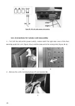
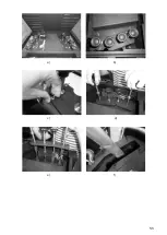
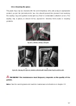
3 – Rivet the terminals of the 220V wire supplying power to the transmitter.
d) e)
4 – Connect the wires on the ON/OFF connector contact (Figure 29-f); direct the wires
through the cable gland to the interior of the unit (Figure 29-g);
f) g)
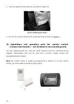
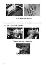
5 – Assemble the interface at the appropriate location on the unit and position the
remote control (On/Off contact) switch to "remote" (Figure 29-h);
h) i)
Summary of Contents for Douro 12
Page 5: ......
Page 60: ...55 a b c d e f ...
Page 66: ...61 ...
Page 67: ...62 ...
Page 68: ...63 ...
Page 89: ...84 23 2 Flow chart Douro 12 kW Flow chart 1 Lighting ...
Page 90: ...85 ...
Page 91: ...86 Flow chart 2 Disabling Note The circulator pump off below 40 C water temperature ...
Page 92: ...87 23 3 Flow chart Douro 17 kW and Douro 23 kW Flow chart 1 Lighting ...
Page 93: ...88 ...
Page 94: ...89 Flow chart 2 Disabling Note The circulator pump off below 40 C water temperature ...