background image

TIG MODE BY POINTS, FULL POwER POINT FEATURE - FPP

To use this feature, you must use an optional two button torch.
If you start the arc using the second button (in a TIG welding process), the FPP (Full Power Point feature) is applied.
The set power is supplied instantly without starting time lapses, ramps or stops. This feature is especially useful for a
quick initial point process.

TIG MODE wITH SECOND LEVEL OF AMPERAGE AND BI-LEVEL FEATURE

If you press the second button having started the process with the first, the machine produces a second level of am-
perage. For TIG processes without pulsed arc, the second amperage value will be the value set in parameter I2. For
pulsed arc TIG processes, either low or high-frequency, the second level is the percentage specified by the Bi-level fe-
ature in the advanced parameter P.34.
For TIG welding with 2T operation, if you press and hold down the secondary button during the down ramp, the wel-
ding current is set according to the second setting level. You can do I

NOM

again if you press and hold down the main

button again during the down ramp.
For TIG welding with 4T operation, start the process with the main button as usual. During welding, apply short pres-
ses using the second button to switch between the first or second setting level. Stop the weld in the normal way by pres-
sing the main button.
By using the adjustment potentiometer you can vary the setting of the rated current from the rated value set on the front
panel to the minimum machine operating value. This allows you to reduce or increase the welding current setting of all
parameters associated with the rated current with a single control.

TIG DC wELDING

Select the DC- polarity in TIG mode to weld different types of steel. We recommend using tungsten electrodes with tho-
rium (red), cerium (grey) or lanthanum (gold).
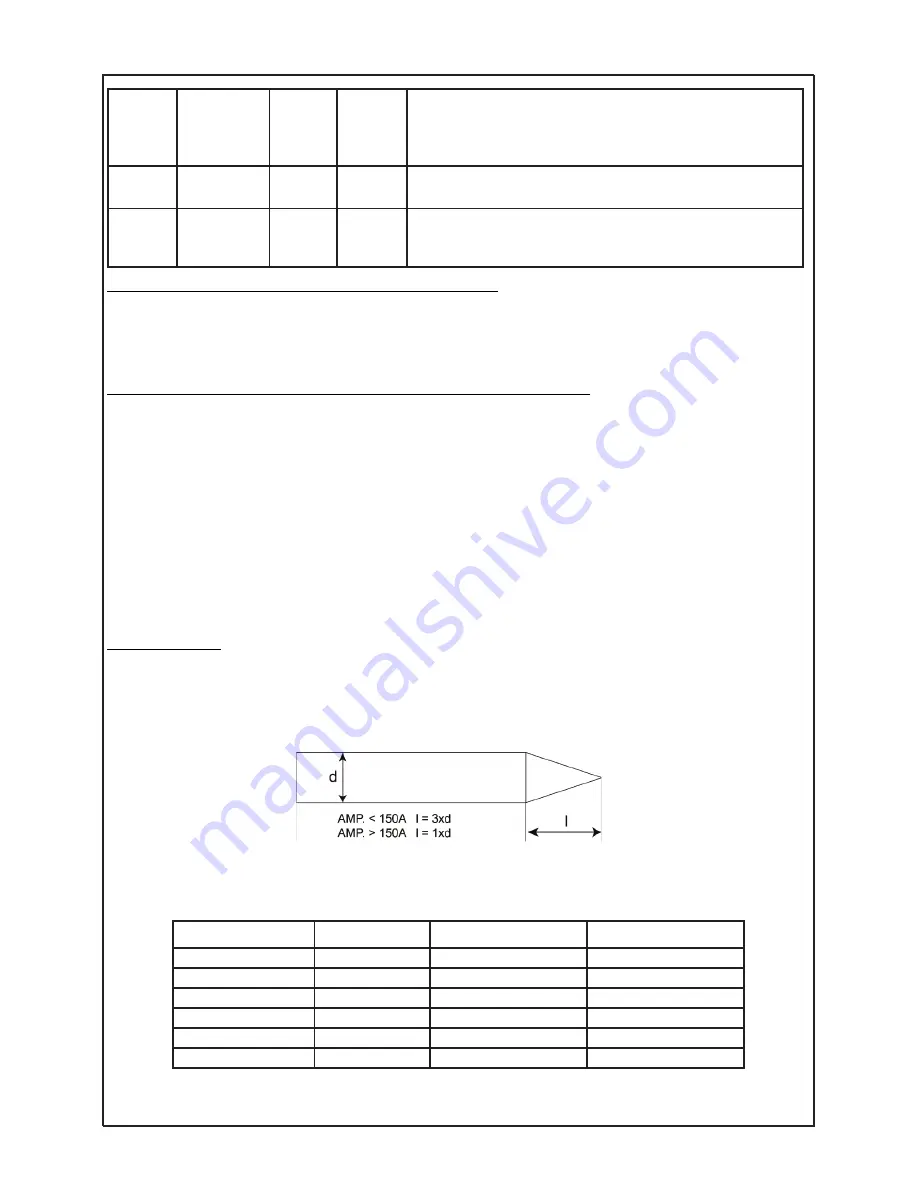
The electrode tip must be sharpened into a cone shape. In this way, the arc is more stable and more energy can be con-
centrated at the weld root. Depending on the amperage used, it is recommended to sharpen the electrode to a greater
or lesser extent.

For TIG DC, depending on the amperage used to weld, a specific electrode diameter, nozzle and gas flow rate is re-
commended. Follow the reference chart below as a guide.

STOP

Final

current

10%

100%

Determines the current value (as a percentage in relation to I

NOM

),

at which the arc finishes. This parameter reduces the possibility
of appearing pores or fissures at the end of the weld bead

STOP

Final current

Time

0,0 sec

10 sec

Determines the time during which the level defined by the I

STOP

parameter will be maintained.

POST GAS

Post gas

time

0,0 sec

10 sec

Time during which gas flows after welding. Necessary to protect
the electrode in TIG mode.

Amps range (A)

Electrode (mm)

Nozzle (mm)

Gas Flow (l/min)

10 - 60

1,0

6,5 / 8,0

5 - 6

60 - 120

1,6

6,5 / 8,0 / 9,5

6 - 7

120 - 170

2,0

8,0 / 9,5

7 - 8

170 - 220

2,4

9,5 / 11,0

8 - 9

220 - 350

3,2

11,0 / 12,5

9 - 10

300 - 420

4

16

10 - 12

SOLTER

SOLDADURA S.L.

AEROTIG AC/DC

39

Summary of Contents for aerotig 4320 DC

Page 1: ...INSTRUCCIONES INSTRUCCIONES PARA EL USO Y EL MANTENIMIENTO LEA ESTE MANUAL ANTES DE PONER EN MARCHA EL EQUIPO INSTRUCTION MANUAL INSTRUCTIONS FOR THE USE AND MAINTENANCE READ THIS MANUAL BEFORE START...

Page 2: ...que se desprendan entren en contacto con la piel No apunte con la antorcha a ninguna parte del cuerpo PROTECCI N DE LOS OJOS Los soldadores y sus ayudantes deben utilizar gafas de seguridad provistas...

Page 3: ...as funciones el equipo permite soldar eficazmente cualquier tipo de electrodo reves tido Se han incorporado m ltiples ajustes para la soldadura TIG destacando principalmente su capacidad para solda du...

Page 4: ...unidad puede soldar a la potencia requerida sin sobre calentarse En el caso que el equipo se sobrecaliente la potencia de soldadura se detendr Aparecer en pantalla una alarma mostrando qu m dulo inter...

Page 5: ...ferencial protege a las personas de contactos directos o indirectos con partes el ctricas El interruptor autom tico se debe elegir en funci n de la placa de caracter sticas del equipo Se aconseja un i...

Page 6: ...unidad de potencia y el otro extremo del tubo al regulador de caudal de la botella de gas Ajuste el caudal de gas a un valor t pico de entre 8 10 l min Un ajuste del caudal inco rrecto puede producir...

Page 7: ...a red ESQUEMA DEL PANEL FRONTAL ATENCI N No pare el equipo mientras se encuentre soldando 1 Pantalla de visualizaci n 2 Visualizaci n Amperios 3 Visualizaci n Frecuencia 4 Visualizaci n voltaje o mm 5...

Page 8: ...e observar en la figura siguiente el panel frontal se divide en varias zonas A PANTALLA E INDICADORES DE ANOMAL AS En la parte superior encontramos la pantalla y los indicadores de anomal a La pantall...

Page 9: ...diente el se al luminoso se desplazar una posici n a la derecha indic ndonos la nueva polaridad de corriente seleccionada Cu ndo se cambie de proceso de MMA a TIG o viceversa se conservan los par metr...

Page 10: ...l valor de Istop la corriente se mantiene en el nivel Istop hasta agotar el tiempo Tistop Fi nalmente la v lvula de gas se cerrar al final del tiempo de post gas Funcionamiento caracter stico para 4T...

Page 11: ...nce el valor deseado efect e una pulsaci n corta para guardar en memoria el valor del par metro modificado el piloto dejar de parpadear para que dar iluminado permanentemente El equipo supervisa todos...

Page 12: ...aci n de par metros de funcionamiento El equipo mostrar entonces un n mero en la pantalla que se encuentra en la secci n PROGRAM Este n mero in dica el n mero de programa que se va a cargar su valor e...

Page 13: ...ferencia de material del elec trodo revestido ajustando la intensidad en cortocircuito Si se produce un cortocircuito prolongado durante m s de un segundo se activa la funci n de anti stick el equipo...

Page 14: ...na el valor de corriente a efectuar durante el tiempo T1 en arco pulsado de baja frecuencia o bien el valor superior de corriente a efectuar durante la mitad del per odo de pulsaci n de alta frecuenci...

Page 15: ...o el pulsador principal Gracias al uso del potenci metro de regulaci n se puede variar el ajuste de la intensidad nominal desde el valor no minal programado en el panel frontal hasta el valor m nimo d...

Page 16: ...6 7 50 130 2 0 8 0 9 5 7 8 90 200 2 4 9 5 11 0 8 9 120 270 3 2 11 0 12 5 9 10 200 350 4 16 10 12 S mbolo Par metro Valor m n Valor m x Descripci n Frecuencia 35Hz 250Hz Indica el n mero de veces que...

Page 17: ...ccione el par metro mediante una pulsaci n corta a continuaci n gire a derecha o izquierda para seleccionar el valor deseado y pulse de nuevo el selector para validar el nuevo valor Puede seleccionar...

Page 18: ...entar la altura del arco para procesos de soldadura MMA OFF Desactivado P 05 No disponible en el presente modelo P 06 No disponible en el presente modelo P 07 OFF ON Habilita la ignici n por arco pilo...

Page 19: ...ara ignici n HF en milisegundos P 33 No disponible en el presente modelo P 34 50 Ajuste funci n Bi Level para TIG por arco pulsado Durante la soldadura al cambiar de pulsador de primario a secundario...

Page 20: ...ante el proceso Para m s informaci n sobre los modos de operaci n de la unidad de refrigeraci n por favor consulte la descripci n del par metro avanzado de ajuste P 36 del presente manual y o el manua...

Page 21: ...rse este tipo de error por la utilizaci n de alargaderas de dema siada longitud o secci n de cable insuficiente En el caso de tener el equipo conectado a un generador deber comprobar que ste cumple co...

Page 22: ...o de calibraci n en la lectura de temperatura auxiliar ER14 Versi n de interfaz de usuario no compatible ER15 Versi n de programa de datos no compatible ER16 Par metros de operaci n corruptos ER17 Sin...

Page 23: ...la ausencia de conexi n de gas de protecci n para el proceso de solda dura que pretende realizar Verifique que el gas de protecci n est conectado a la en trada situada en la parte posterior del equip...

Page 24: ...informaci n consulte la secci n anomal as y defectos del presente manual La corriente de soldeo no se corresponde con el nivel ajustado CAUSA SOLUCI N Dispone de un control anal gico remoto mal ajusta...

Page 25: ...echo y la pinza de masa al izquierdo La pieza est sucia Elimine la suciedad o restos de pintura Corriente de aire excesiva Una corriente de aire puede desplazar el gas de pro tecci n y afectar al arco...

Page 26: ...el electrodo son correctos para su aplicaci n Este aviso no condiciona el funcionamiento del equipo El arco pulsado no funciona CAUSA SOLUCI N No est habilitado el modo TIG por arco pulsado Verifique...

Page 27: ...and their assistants must use safety masks or goggles with filters which stop harmful radiation entering the eyes Use special screens to observe the welding area during the process FIRE PROTECTION Th...

Page 28: ...the machine is equipped with adjustable anti stick hot start and arc force features Thanks to these features you can weld effectively with any type of coated electrodes For TIG welding the equipment h...

Page 29: ...eated The fans turn until the internal temperature is below 40 C The machine will automatically reset when it reaches a safe temperature again However it is recommended to wait at least 5 minutes befo...

Page 30: ...t be chosen according to the equipment nameplate A switch with an intensity time ratio of the slow type D curve is recommended to prevent false triggering HANDLING OF THE MACHINE To handle the power u...

Page 31: ...t the gas tube to the rear nozzle of the power unit and the other end of the tube to the gas cylinder flow regulator Set the gas flow rate to a typical value of 8 10 l min A wrong flow setting can cau...

Page 32: ...ON Do not stop the machine while welding 1 Display 2 Amps visualization 3 Frequency 4 Voltaje or mm visualization 5 Percentage 6 Time 0 1s 7 Overtemperature 8 Common problems 9 Pre gas time 10 Startin...

Page 33: ...ront panel is divided into several areas A DISPLAY AND FAULT INDICATORS The display and fault indicators can be found at the top of the control panel The display shows the value of the para meters con...

Page 34: ...process or vice versa the previously set parameters for the process are maintained i e you can simultaneously set different power levels for MMA and TIG processes When you change the welding mode the...

Page 35: ...ly the gas valve will close at the end of the post gas time Characteristic operation for 4T In this case the arc will begin on the first pulse and remain while this continues the machine will supply t...

Page 36: ...er in me mory the light will stop flashing and will remain fixed The machine monitors all welding parameters associated with TIG AC and determines whether the selected electrode diameter is correct fo...

Page 37: ...mode to load a specific setting of operating parameters The machine then displays a number on the screen in the PROGRAM section This number indicates the number of the program to be loaded and its va...

Page 38: ...short circuit current If a prolonged short circuit of more than a second occurs the anti stick function is ac tivated the machine stops supplying power to allow to pull off the electrode If you use cu...

Page 39: ...during the time T1 in low frequency pulsed arc or the highest current value to be supplied halfway through the high frequency pulse period I 2 Secondary pulsed current 10A 350A If the machine does not...

Page 40: ...r you can vary the setting of the rated current from the rated value set on the front panel to the minimum machine operating value This allows you to reduce or increase the welding current setting of...

Page 41: ...4 16 10 12 Symbol Parameter Min Value Max value Description Frequency 35Hz 250Hz Indicates the number of times the current changes its polarity per se cond A high frequency concentrates the arc cone t...

Page 42: ...th a short press then turn left or right to select the desired value Press the selector to validate the new value You can select other parameters or return to the settings chart Example 71h 30 minutes...

Page 43: ...ailable in this model P 11 Normal Allows you to select the type of main button Normal for open NO or inverted for closed NC P 12 Normal Allows you to select the type of secondary button Normal for ope...

Page 44: ...milliseconds P 33 Not available in this model P 34 50 Bi Level feature setting for pulsed arc TIG During welding if you change from the primary to secondary button an average am perage level correspo...

Page 45: ...t please see the description of advanced setting pa rameter P 36 in this manual and or the Aerocool cooling unit manual Interval Action Weekly Check the condition of wiring and external accessories Bl...

Page 46: ...e of excessively long extension cords or insuffi cient cable section If the machine is connected to a generator you must ensure that it meets the recommen ded specifications and that the voltage is pr...

Page 47: ...ization between main control unit and user interface is pending ER18 Detection of different user interface from the original ER19 User interface is not supported ER20 Data memory is not initialised ER...

Page 48: ...cooling unit flow transducer reading is incorrect This error can be caused by inco rrect priming of the cooling system or the clogging of the internal filter A 13 Not available in this model A 14 Not...

Page 49: ...of the power unit For more information see the anomalies and defects section of this manual The welding current does match the set level CAUSE SOLUTION It has a wrongly set remote analogue control Ch...

Page 50: ...educe the pre gas time Electrical discharge in the torch Replace the TIG torch for a new one Excessive consumption of the tungsten electrode in TIG mode CAUSE SOLUTION Earth and torch connections inte...

Page 51: ...lec trode s diameter have been set properly for your appli cation You can ignore this alarm if you are sure that all parameters are ok The pulsed arc doesn t works CAUSE SOLUTION Pulsed arc is not ena...

Page 52: ...e Normen kamen zur Anwendung EN 60974 1 EN60974 10 Technical Department Campdev nol 7 2013 SOLTER SOLDADURA S L NIF B 17245127 CTRA NACIONAL 260 KM 122 17530 CAMPDEVANOL GIRONA SPAIN CERTIFICADO DE GA...

Page 53: ...SOLTER SOLDADURA S L AEROTIG AC DC A2...

Page 54: ...SOLTER SOLDADURA S L AEROTIG AC DC A3...

Page 55: ...SOLTER SOLDADURA S L AEROTIG AC DC A4...

Reviews: