


4.7 Communication C
able Assembly
The RHI-5G Series inverter uses RS485 cable to communicate with the Meter and CAN to
communicate with the battery's BMS. The image below shows the assembly of the RS485/CAN
communication cables.
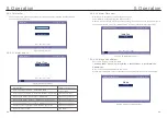
Procedure for connecting the CAN cable:
1. Take out the CAN cable (terminal marks ‘CAN' on one end and 'to Battery' on the other end).
2. Unscrew the swivel nut from CAN port.
3.
Insert the RJ45 terminal with CAN label into the CAN port, then fasten the swivel nut.
4.
Connect the other end to the battery.
NOTE:
Lead-Acid and other older-technology battery types require experienced
and precise design, installation and maintenance to work effectively.
For RHI series inverters there is no temperature compensation , thus client
need BTS (battery temperature sensor) which is connected to CAN port at
one side and battery negative pole at the other side.
BTS is optional. For further information please contact the sales manager.
For lead-acid battery , battery SOC calculation may not be accurate
according to battery inconformity between cells, battery aging or other
specifications of lead-acid battery etc.
NOTE:
For CAN cable pin 4 (blue) and pin 5 (white-blue) are used for the
communication.
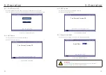
Procedure for connecting the RS485 cable:
1. Take out the RS485 cable (terminal marks ‘RS485' on one end and 'to Meter' on the other end).
2. Unscrew the swivel nut from RS485 port.
3. Insert the Two-pin terminal with RS485 label into the RS485 port, then fasten the swivel nut.
4. Connect the other end to the Meter.
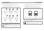
An external ground connection is provided at the right side of inverter.
Prepare OT terminals: M4. Use proper tooling to crimp the lug to the terminal.
Connect the OT terminal with ground cable to the right side of inverter. The torque is 2Nm.
4.8 External ground connection
Figure 4.11
Connect the external grounding conductor
4. Installation
4. Installation
-
+
Figure 4.10
CAN
FN
Set
-
R
_
P
Com
Run
OR
.18.
.19.
NOTE:
The CAN cable enables the communication between the inverter and Lithium
batteries.


