69
68
▲
▲
ASSEMBLY
1. Unpack all parts and dispose of the packaging material, especially the plastic
bags (suffocation hazard for children!) as well as potential advertisement stickers
and labels.
2. Spread all parts that need assembly out in front of you.
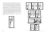
3. Place the base in front of you. Remove the angled screw (
a
) from the standing
post. Insert the end of the standing post that previously held the screw into the
hole in the base and connect both parts through the bottom side of the base
with the angled screw (
a
). (
Fig. 1
)
4. Push the lower end of the ventilator chassis all the way onto the standing post
and fasten both parts with the blocking screw (
9
). (
Fig. 2
)
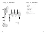
5. Unscrew first the rotor blade nut (
2
) and then the rear nut (
4
) from the mo-
tor shaft (
6
). The rotor blade nut has to be unscrewed clock wisely (towards
“Loosen”), the rear nut has to be unscrewed counter clock wisely (towards
“Loosen”).
6. Push the rear protection grid onto the motor shaft over the thread and turn it
so that the 3 positioning pins on the motor chassis hold the rear protection grid
in position (tear shaped recess has to stand above the triangular positioning
pin). (
Fig. 3+ 4
)
Fig. 2
Fig. 3+ 4
Fig. 1
a


