


00-WTS-DB REV 1 11/2005
2
Wiring Cont’d
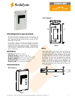
CAT-5 Wiring:
Jumper Configuration
The WTS-DB has 3 jumper configurations. The default jumper
position is JP2 only. Other jumper configurations are reserved
for future use and not applicable at this time.
CAT-5 Input Assignment:
When using the CAT-5 wiring, the M2 controllers will automati-
cally assign it’s inputs to pre-defined locations:
Figure 4
M2
M2V
Temperature Sensor
Input 1 (AI1)
Input 1 (Zone
Temp)
Setpoint
Virtual 1 (VI1)
Virtual 1 (VI1)
Light Level Sensor
Virtual 2 (VI2)
Virtual 2 (VI2)
Table 1
Figure 5
M2-HH Commissioning Tool
The WTS-DB has a small 5 pin connector on the bottom end of
the device which is used to connect the M2-HH hand held com-
missioning tool. Please see the 00-M2-HH documentation for
Installation
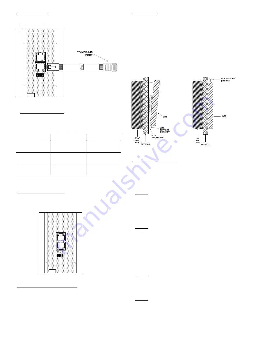
The WTS-DB backplate will install easily onto any 2”x4” electrical box
with the supplied 1” screws. An electrical box is not necessary for
proper installation of the WTS-DB. The 1” screws have a flat head, if
longer screws are needed, please make sure they have a flat head.
Once the backplate is installed and wiring is completed, install the
WTS-DB sensor onto the backplate at an angle starting at the bot-
tom of the sensor as shown in figure 6.
After sliding the WTS-DB sensor onto the support bracket of the
backplate, rotate the sensor towards the wall and secure the WTS-
DB sensor in place by installing the supplied set screw as shown in
figure 7.
Figure 6
Figure 7
Modes of Operation
The WTS-DB has 4 configurable modes of operation. Each of the 4
modes displays the zone temperature (either °F or °C) until a button
is pushed on the unit. The different modes only change the way the
setpoint is displayed/used. These different modes of operation are
listed below.
Mode 1
This mode is the default mode for the WTS-DB. This gives the user
an interface to view the room temperature and adjust the setpoint
numerically. When the user changes the zone setpoint on the WTS-
DB, the value will be set to Virtual Input #1. By default, the user
can set the zone setpoint from 55 to 85.
Mode 2
This mode gives the user an interface to view the room temperature
numerically, but the setpoint for the zone is displayed via the 7 LED
level indicator. This 7 LED level indicator has 3 red LED’s and 3 blue
LED’s and 1 green LED in between the 3 red and 3 blue LED’s.
When the user adjusts the zone setpoint the value will be set to
Virtual Input #1. By default, the 7 LED level indicator has a range of
+3 to –3 where 0 will be set to Virtual Input #1 when the middle
green LED is set. See Figure 8 for details of the LED level indicator.
Mode 3
This mode eliminates the user zone setpoint all together. It does
however allow the user to view the current zone temp and send a
system override.
Mode 4
This mode is the same as Mode 3, but the LED level indicator is used
to display how warm or cool the room is based on Virtual Input #1
which would be set by a device other than the WTS-DB (ie. ICMS
graphic). With the highest red LED lit, the room is 3 or more de-
grees warmer than Virtual Input #1. With the lowest Blue LED lit,
the room is 3 degrees cooler than Virtual Input #1