background image

D

Dy

yn

na

am

miic

cs

s S

Se

ec

ct

tiio

on

n

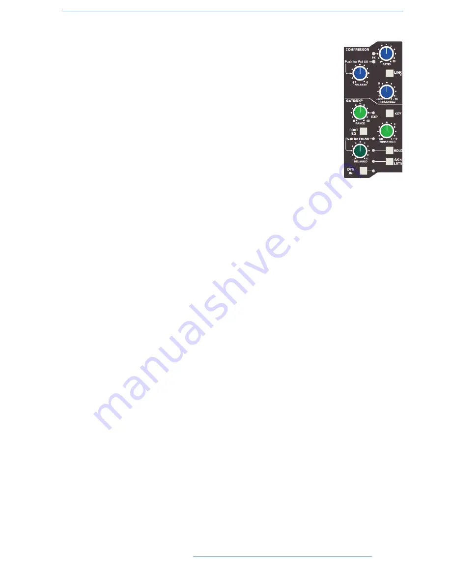
The Dynamics section contains a compressor section identical to that of the 9000K series
and  also  found  in  SSL's  X-Logic  range  of  outboard  processing  units.  In  normal  use,  the
compressor’s  true  R.M.S.  side  chain  and  over-easy  soft  ratio  function  provide  a  very
transparent compression action even with large amounts of gain reduction. The fast attack
option offers the classic SSL compressor sound normally associated with its use on drum and
percussion sources. Selecting Peak (

PK

) mode defeats the over-easy soft ratio, modifies the

release curve and attack times, and unleashes a far more aggressive sounding compressor
ideal for more radical sonic shaping.

The Gate/Expander section is a new variant of SSL’s classic 4000 series three-control design.
It features the choice of a steep gate or gentle expander slope, with optional fast attack. The
new ‘Hold’ (HOLD) option flips the variable release (REL) control to function as a variable
hold-off time with a fixed release curve.

The complete section is switched in or out of circuit using the 

DYN IN

button (see also

Central Routing Control

). When the dynamics section is in circuit, the 

DYN

box on the

channel TFT display is highlighted.

Individual controls act as follows:

Compressor

RATIO

— When turned to 1:1, the compressor section is inactive. Turning the control clockwise increases the

compression ratio until it reaches a true limit mode at the fully clockwise position. Pressing the 

RATIO

knob

switches the compressor to peak sensing, and replaces the ’over easy’ characteristic with a hard knee, providing an
alternative voicing for some instruments. The 

PK

LED lights to indicate that this option has been selected.

THRESHOLD

— Whenever a signal exceeds the level set by this control, the compressor will start to act at the

ratio set by the 

RATIO

control. This control, in conjunction with the Ratio setting, provides automatic make-up

gain, so as you lower the threshold and introduce more compression, the output level is increased, maintaining a
consistent output level.

RELEASE

— Sets the time constant (speed) with which the compressor returns to normal gain settings once the

signal has fallen below the compressor threshold. This control also incorporates a push-push switch which selects
a very fast attack time as an alternative to the standard time constant.

Gate/Expander

This section can act as a Gate or as a 2:1 Expander when the 

RANGE

pot is pressed. The 

EXP

LED indicates that

Expand mode has been selected.

RANGE

— Determines the depth of gating or expansion. When turned fully anticlockwise (Range = 0), the section

is inactive. When turned fully clockwise, an attenuation range of 40dB can be obtained.

2

2--5

5

C

Co

on

ns

so

ol

le

e  O

Op

pe

er

ra

at

tiio

on

ns

s

D

Du

ua

al

liit

ty

y  S

SE

E  O

Op

pe

er

ra

at

to

or

r’’s

s  M

Ma

an

nu

ua

al

l

Summary of Contents for Duality SE

Page 1: ...Duality SE O OP PE ER RA AT TO OR R S S M MA AN NU UA AL L Part Number 82S6DUA20D ...

Page 2: ...Ku Tokyo 151 0051 Japan 81 0 3 5474 1144 7 bis rue de la Victoire le Blanc Mesnil Paris 93150 France 33 0 1 48 67 84 85 Via Timavo 34 20124 Milano Italy 39 0 39 2328 094 Visit SSL at URL http www solidstatelogic com Solid State Logic All Rights reserved under International and Pan American Copyright Conventions Duality Solid State Logic and SSL are trademarks of Solid State Logic All other product...

Page 3: ... ns so ol le e O Op pe er ra at ti io on ns s Section Contents 2 i Section Index 2 iii Overview 2 1 An Introduction to Split Mode 2 2 Routing and Signal Flow 2 2 DAW I O Labelling 2 2 Channel Strip 2 3 Introduction 2 3 Channel Input Section 2 4 Dynamics Section 2 5 Filters 2 7 Equaliser 2 7 Insert 2 7 Channel Output CHOP 2 8 Signal Processor Routing 2 8 Channel Sends 2 9 Channel Pan 2 10 D pot and...

Page 4: ...ures Summary 3 1 Console Focus 3 2 DAW Layers 3 3 Connecting Duality to DAWs 3 5 Connecting via physical MIDI ports 3 6 Connecting via ipMIDI 3 7 DAW Control Operations 3 13 D pots 3 13 The Master Control Panel HUI Mode 3 15 Channel Banking Controls 3 15 DAWWindow Buttons 3 15 DAW Utility Buttons 3 16 Modifier Buttons 3 16 The Default Button 3 17 Channel Functions 3 19 DAW Meters 3 19 Channel Fade...

Page 5: ...diting Plug In Parameters Parameter Mode 3 35 Soft Keys 3 37 Automation Enables 3 37 Automation Modes 3 37 EditTools Menu 3 38 Edit Modes Menu 3 38 Status Group Menu 3 38 Function Keys 3 39 EDIT Menu 3 39 SSL Menu 3 39 Working with DAW Automation 3 41 Automation Enables 3 41 Automation Modes 3 41 TRIM Mode 3 41 Automation Status Display 3 42 Suspending Automation 3 42 Writing Automation Write to S...

Page 6: ... iii Overview 5 1 Key features 5 1 Automation and Projects 5 3 Working with Projects andTitles 5 4 Automation in the Duality SE Remote 5 5 Operation 5 7 Activating the Automation System 5 7 List Mix Menu 5 7 Creating A New Mix Pass 5 8 Mix Running 5 10 Dedicated Automation Buttons 5 11 Join and Revise 5 12 Discard 5 13 Updating a Mix Pass 5 13 Protection Modes 5 14 Switch Automation 5 16 Automatio...

Page 7: ...rTotal Recall Setups 6 3 Backing up a Project 6 4 Restoring a Project 6 4 Mixes Tab 6 5 Total Recall Tab 6 6 Channel Tabs 6 7 Externals Tab 6 8 About Tab 6 9 S Se ec ct ti io on n 7 7 B Bl lo oc ck k D Di ia ag gr ra am ms s Annotated Channel Layout Duality Channel Strip block diagram Annotated Centre Section Layout Duality Master Section Block Diagram S Se ec ct ti io on n 8 8 D Du ua al li it ty...

Page 8: ...This page is intentionally almost blank V VI I I In nt tr ro od du uc ct ti io on n D Du ua al li it ty y S SE E O Op pe er ra at to or r s s M Ma an nu ua al l ...

Page 9: ...Duality SE O OP PE ER RA AT TO OR R S S M MA AN NU UA AL L S SE EC CT TI IO ON N 1 1 I IN NT TR RO OD DU UC CT TI IO ON N Part Number 82S6DUA20D ...

Page 10: ...This page is intentionally almost blank ...

Page 11: ...mary 1 1 Console Feature Summary 1 1 Exceptional Signal Processing 1 2 CreativeVersatility 1 2 DAW Controller 1 2 Controller Features Summary 1 3 System Options 1 3 A Ab bo ou ut t t th hi is s m ma an nu ua al l 1 1 5 5 Conventions Used 1 5 Contacting Solid State Logic 1 5 1 1 i i I In nt tr ro od du uc ct ti io on n D Du ua al li it ty y S SE E O Op pe er ra at to or r s s M Ma an nu ua al l ...

Page 12: ...This page is intentionally almost blank 1 1 i ii i I In nt tr ro od du uc ct ti io on n D Du ua al li it ty y S SE E O Op pe er ra at to or r s s M Ma an nu ua al l ...

Page 13: ...ording engineer who has previously used SSL consoles K Ke ey y F Fe ea at tu ur re es s S Su um mm ma ar ry y Combined large format SSL console and DAW controller Legendary SuperAnalogue mic preamps and signal processing NewVHD Variable Harmonic Drive preamp stage Comprehensive monitoring up to 5 1 surround with multiple loudspeaker support Direct control of DAW recording editing and mixing functi...

Page 14: ...own mix main outputs 24 track busses 2 Stereo Cue plus four Aux busses on all channel modules with EFX re assign system to feed track busses and channel output Wide range of solo modes including Solo In Front 4 stereo echo returns with full mix foldback routing Unrivalled studio monitoring section with comprehensive user options Hi visibility channel TFT screens for metering and optional Total Rec...

Page 15: ...our DAW Simple switching between console layer and DAW control layer Full remote control implementation Operation independent of platform works with Pro Tools Nuendo Logic Audio and others MIDI over Ethernet for enhanced control of two DAW systems S Sy ys st te em m O Op pt ti io on ns s Multi operator Total Recall including Autoscan for accurate resetting of session parameters Comprehensive autom...

Page 16: ...This page is intentionally almost blank 1 1 4 4 I In nt tr ro od du uc ct ti io on n D Du ua al li it ty y S SE E O Op pe er ra at to or r s s M Ma an nu ua al l ...

Page 17: ...h from time to time C Co on nv ve en nt ti io on ns s U Us se ed d Some typographical conventions have been used in this manual to help distinguish explanatory text from the text referring to console items They are as follows Switch cap engravings on the console are usually in UPPERCASE eg SOLO Silk screened text on the console s control surface can be either UPPERCASE eg DYNAMICS or lowercase bol...

Page 18: ...This page is intentionally almost blank 1 1 6 6 I In nt tr ro od du uc ct ti io on n D Du ua al li it ty y S SE E O Op pe er ra at to or r s s M Ma an nu ua al l ...

Page 19: ...Duality SE O OP PE ER RA AT TO OR R S S M MA AN NU UA AL L S SE EC CT TI IO ON N 2 2 C CO ON NS SO OL LE E O OP PE ER RA AT TI IO ON NS S ...

Page 20: ...This page is intentionally almost blank ...

Page 21: ...l Cut and Solo 2 11 Channel Fader 2 11 Fader Grouping 2 12 Fader Links 2 12 The Channel TFT Screen 2 14 T Th he e C Ce en nt tr re e S Se ec ct ti io on n 2 2 1 17 7 Introduction 2 17 Power Supply Indicators 2 17 Central Routing Panel 2 18 Main Output Functions 2 20 Main Bus Compressor 2 21 Master Fader 2 22 Track Bus Master Controls 2 23 Monitoring 2 24 Cue FX Send Master Controls 2 33 Foldback a...

Page 22: ...This page is intentionally almost blank 2 2 i ii i C Co on ns so ol le e O Op pe er ra at ti io on ns s D Du ua al li it ty y S SE E O Op pe er ra at to or r s s M Ma an nu ua al l ...

Page 23: ...F F Fader 2 11 2 22 Fader Grouping 2 12 2 40 FILT to INP button 2 4 2 7 Filters 2 7 Foldback 2 33 2 36 FX Sends 2 9 G G Gate 2 5 H H H P button 2 34 Headphone outputs 2 34 Hi Z button 2 4 I I INPUT FLIP function 2 4 2 19 Insert 2 7 K K KEY button 2 6 L L Labelling DAW I O 2 2 LFE 2 39 LINK button dynamics 2 6 M M Main Output Functions 2 20 Metering 2 14 2 26 2 41 Misc Options 2 35 Mix Reassign Mat...

Page 24: ...2 32 Solo In Front 2 32 SPLIT button 2 8 Split Mode 2 2 2 8 SRC SEL button 2 8 Stereo Mix Matrix 2 39 Stereo Returns 2 34 T T Talkback 2 36 TO S ch button 2 7 Track Bus Master Controls 2 23 V V Variable Harmonic Drive 2 4 C Co on ns so ol le e O Op pe er ra at ti io on ns s 2 2 i iv v D Du ua al li it ty y S SE E O Op pe er ra at to or r s s M Ma an nu ua al l ...

Page 25: ...hniques in an integrated high quality and robust design coupled with all of the sonic benefits expected from a Solid State Logic console SSL s extensive design experience has been utilised to create the ultimate capture path for up to 96 simultaneous inputs into the DAW where recorded signals can be edited processed and mixed via Duality SE s control surface The signal paths can then be either sum...

Page 26: ... mixes or post DAW processed sends R Ro ou ut ti in ng g a an nd d S Si ig gn na al l F Fl lo ow w As you read through the following pages you may find it useful to refer to the signal flow diagrams in the appendices section at the end of this manual In order to understand signal flow through Duality SE s various operational modes first we need to discuss how your DAW I O unit is connected to the ...

Page 27: ... Direct Output CH OP is provided Each channel has comprehensive routing for EQ and filter dynamics and insert send return points The channel strip can be divided into five distinct functional sections See left 1 Channel input 2 Dynamics 3 EQ and filter 4 Cue Stereo and FX outputs 5 Channel output pan Note that a number of channel parameters are adjusted via the Central Routing Panel in the Centre ...

Page 28: ...gnal colouration Pressing the DRV IN button routes the input signal to a completely different preamp featuring the SSL developed VHD Variable Harmonic Drive circuitry VHD emulates the characteristics of a classic valve front end but with the option to tailor the harmonic mix when the preamp is overdriven by adjusting the DRIVE pot In conjunction with the 24dB PAD and Hi Z input impedance option VH...

Page 29: ...ection is inactive Turning the control clockwise increases the compression ratio until it reaches a true limit mode at the fully clockwise position Pressing the RATIO knob switches the compressor to peak sensing and replaces the over easy characteristic with a hard knee providing an alternative voicing for some instruments The PK LED lights to indicate that this option has been selected THRESHOLD ...

Page 30: ...ther section Don t try to link two gates using the LINK button when you want the signal on one to open the other If you need to achieve this effect take a keying signal from one section to trigger the other The easiest way to do this is by patching from the insert send of the source channel into the Key input see below of the destination channel and selecting the KEY button on this channel The KEY...

Page 31: ... characteristic of the original G Series EQ The individual bands function as follows HF high frequency shelving equaliser switchable to fixed Q parametric BELL HMF high frequency parametric mid band equaliser LMF low frequency parametric mid band equaliser LF low frequency shelving equaliser switchable to fixed Q parametric BELL The EQ IN button located next to the insert buttons routes the channe...

Page 32: ...the channel strip offers a new approach to in line tracking on an analogue console by returning the DAW output back into the channel path just after the channel output pick off point By using INPUT or PRE FADE as the channel output source clean or processed signals are routed to the DAW input with the option to use the remaining channel processing and routing to monitor the DAW return in the analo...

Page 33: ...ue output to Cue B by holding down the SET EFX CUE B button then pressing the stereo cue gain pot this toggles the selection through Cue B EFX and Cue A off Master controls for the Cue A and B busses can be found in the centre section Pan your mono source across the stereo cue bus outputs with the LR pan control The stereo cue send is turned on off by means of a push push switch mounted on the sen...

Page 34: ...d defeats 5 1 panning to the busses The channel panning section features XY style 5 1 panning via LR Left Right and FR Front Rear controls with additional LFE and Focus functions The LFE control feeds a variable amount of the channel output to a dedicated LFE subwoofer bus see more on this in the Centre Section The Focus control alters the proportion of input signal fed to the front Left Right bus...

Page 35: ...hannel or assign the plug in editor Pro Tools only Tallies in the channel meter display Record Ready and Edit status regardless of whether the console is in DAW Focus Mode see Section 3 for more details C Ch ha an nn ne el l C Cu ut t a an nd d S So ol lo o The CUT and SOLO buttons above the traditional scribble strip function in the normal way providing muting and solo auditioning of channels C C...

Page 36: ...grouping system With a Fader Link any fader or non latching switch operation can be applied to all the channels in the link Faders retain any existing level offsets provided no fader in the link reaches the upper or lower extremes of the fader scale If any member of a link reaches the end of its physical travel no member of the link can move beyond this point To access Fader Links press the Lnks s...

Page 37: ...isting links scroll to and select the link Channels can be added or removed as described above SuspdSel SuspdAll Links can be globally or individually suspended at anytime A link that is suspended will allow you to move all the faders in the link independently If a link is highlighted then the SuspdSel key will deactivate the selected link and suspended will be shown next to the link number SuspdA...

Page 38: ...nal paths in each channel including the channel inputs the channel fader and the channel output as well as providing an indication of which processing element is actually in circuit Once again colour coding is used for ease of recognition Channel Metering A single peak meter indicates either analogue channel signals or DAW levels according to selection of the Console DAW Focus button see Section 3...

Page 39: ...onfirms that channel is currently the selected channel REC indicates the Record Ready status of the associated DAW track and EDIT shows if the DAW channel associated with that channel strip is currently assigned to the plug in editor ProTools only See Section 3 for more details Note that Record Ready and Edit status will be indicated regardless of whether the console is in DAW Focus Mode or not 2 ...

Page 40: ...1 2 3 4 2 2 1 16 6 C Co on ns so ol le e O Op pe er ra at ti io on ns s D Du ua al li it ty y S SE E O Op pe er ra at to or r s s M Ma an nu ua al l ...

Page 41: ... facilities P Po ow we er r S Su up pp pl ly y I In nd di ic ca at to or rs s Before we cover the more interesting features of the centre section take a moment to acquaint yourself with the console s power supply indicators If you suspect a hardware problem and one of the LEDs described below is not lit there may be a power supply fault The LEDs which display the current state of power rails withi...

Page 42: ...ayed in the right hand TO window and indicated on the channel meter display To increment the range either use the buttons or press a second channel select button to select the highest channel in the range the highest channel is shown in the TO window Once a channel has been selected The Central Routing Panel s SELECT button allows non contiguous arrays of channels to be added or removed from the c...

Page 43: ...d even pairs 5 1 panning divides the track busses into four 6 channel groups EFX TO TRK replaces the channel feed to the Track busses with the active EFX send output Stereo Cue EFX sends are automatically routed to odd even pairs When SET AUX is selected changes made to Cue Stereo and FX source and destination routing and On Off state on any of the selected channels will be copied to all selected ...

Page 44: ...to the selected bus ses This functions as single stereo unit inserted on a chosen stereo bus or as a 5 1 compressor when in 5 1 mode see below The single master FADER is assigned to individual stereo mix stems or as a 5 1 master fader in 5 1 mode The fader can control the same level of all three stereo busses simultaneously but can only set the level for one bus at a time If not fader controlled t...

Page 45: ...hable in six steps between 0 1 and 30 ms and the RELEASE time is selectable between 0 1 and 1 2 seconds in five steps The AUTO release selection adjusts the release time according to the signal envelope The gain MAKE UP simply acts as a level control to compensate for the lowered level that is a consequence of compressing the signal This control may be set so as not to change the overall output le...

Page 46: ...right is for use with the 10dB function selected via the main bus select matrix see previous page The automation status button and LEDs fitted on this fader are used with the optional automation system Following the injection of talkback and tone see later the main output busses feed D connectors on the centre section connector panel All the main mix busses are provided with LCD metering above the...

Page 47: ...connector on the centre section connector panel An AFL function post tone and talkback inject is provided for each bus The AFL signal is intelligently assigned to left and right AFL busses Selecting AFL on a single Track bus output will route signal to both left and right AFL busses Selecting AFL on odd and even numbered Track bus outputs will route the odd numbered output to the left AFL bus and ...

Page 48: ...rought in via the EXT A monitor source selector see below The STEREO button folds down the 5 1 inputs to the monitor path via a 5 2 gain compensated matrix which also provides the Mon feed to the foldback outputs and feeds the result to left and right monitor outputs MONO can be selected with or without STEREO and sums the left and right monitor busses feeding the result equally to the left and ri...

Page 49: ...ction connector panel The two 5 1 outputs Main and Alt and the two Mini outputs feed two 25 way D type connectors MON A and MON B the two Mini outputs Mini A and Mini B also feed individual XLRs for left and right External Source Selectors Two external monitor source selectors are provided EXT A has four 5 1 inputs These may be fed by any source of six channels or less The MIX selection provides a...

Page 50: ...e decoder inputs Selecting EXT A and INS will monitor the insert return if no source is selected on External B you will hear the ExternalA signals through the encoder and decoder If a source is selected then you will hear the decoded output of External B Selecting EXT B and INS and selecting a source on External B will monitor External B Selecting EXT B and INS with no source selected on External ...

Page 51: ...ound onA function This allows you to switch to the alternative LCR speakers connected to the ALT 5 1 Main B output and still maintain full surround monitoring A further option A2B see next page enables the subwoofer output to be included in this arrangement LRA Similar to the SRA function except that the LCR monitor feeds are locked to the Main A outputs but an alternative set of surround speakers...

Page 52: ... for each set of speaker outputs like the loudspeaker level calibration so it is possible to have Bass Management enabled on one set of speakers and not on others LF0 Normally the LFE bus level is increased by 10dB post the main monitor level control as this is a requirement for DVD playback If you are mixing for SACD or any other format that requires unity gain on the LFE channel select LF0 to re...

Page 53: ...he position you wish to correspond to the calibrated level A level setting of 8 5 will provide 10dB of additional gain in hand Now select the required monitor system Main 5 1 ALT 5 1 MINI A or MINI B Select the CAL menu Pressing either AL or AR or AC will send pink noise to the Left or Right or Centre loudspeakers respectively Adjust the level for the required SPL eg 85dBa C weighting slow respons...

Page 54: ...ted and the six monitor cut buttons will light uncut the left output and with the bass management turned on note that theBMN selection in the BASS menu is duplicated in the CAL menu adjust the LFG gain for a flat low end response Cut the left output uncut the right output and check this has a flat low end response Repeat for all channels Depending on how well matched the monitors are you may have ...

Page 55: ...evel to match that displayed on your Monitor Level display Note that the monitor gain corresponding to 85dB SPL can be set in the Monitor options CAL page 1 by adjusting the main monitor level control to give an SPL of 85dB then pressing the 85dB switch Note that if you make a change to this value in the Setup menu while running in Calibrated mode this change will not be reflected until you come o...

Page 56: ... and desk output ISO To solo isolate a number of channels select ISO press the SOLO buttons on all channels to be isolated then deselect ISO The SOLO switches on isolated channels will flash Solo isolated channels can be set to automatically solo in AFL mode via the Isolated channels AFL on solo option in the SSL Misc Setup menu ALT Makes channel SOLO buttons intercancel with each other so that so...

Page 57: ...sses see Centre Section Metering F Fo ol ld db ba ac ck k a an nd d H He ea ad dp ph ho on ne e O Ou ut tp pu ut ts s The console provides three stereo outputs Foldback A and B intended for use in the studio for headphones or LS playback plus a stereo headphone feed for control room use a socket for this is provided beneath the buffer rail in the centre section The foldback outputs feed 1 4 jacks ...

Page 58: ...on at the bottom of the Stereo Return The Routing Panel display will change to read St 01 02 03 and the MIX A MIX B and MIX C buttons above can be used to assign the selected Stereo Return to the required bus ses The BALANCE pot provides a differential Left Right gain trim for the stereo input signal This is followed by a variable stereo WIDTH control which can reduce the stereo image to a mono ce...

Page 59: ...faders to 0dB IND When selected pressing any fader s fader button will set that fader to 0dB The IND button flashes to indicate that it is active OFF Moves all faders to UNDO Reverses the last action Note that there is one level of undo The button lights to indicate that an undo is available 2 2 3 35 5 C Co on ns so ol le e O Op pe er ra at ti io on ns s D Du ua al li it ty y S SE E O Op pe er ra ...

Page 60: ...ts with talkback F B A and F B B Adds or optionally replaces talkback to the associated foldback outputs after the level and cut controls EXT T B Sends talkback to an external feed available via a 1 4 jack on the connector panel Level is adjusted using the Talkback Out pot see above TB ALL feeds talkback to the foldback sends and the external talkback output LISTEN Injects an external mic signal c...

Page 61: ...k switches and Listen switch options Auto inhibits the switch when the transport is in the status indicated In the case of the red light Auto forces the red light on when the transport is in play record TB switches disable Listen This allows the Listen function to be switched off when talkback is activated thus avoiding feedback problems TB to FB Sums Replaces When assigning talkback to foldbacks ...

Page 62: ...ne to pink noise Note that the pink noise level can only be adjusted using the Pink Cal preset The LEVEL control adjusts the level of the tone generator from 25dBu to 20dBu When fully anticlockwise a preset Cal level is selected that can be calibrated using the multiturn preset located below the level control a red LED lights to show when the level control is in the calibrated position When OSC ON...

Page 63: ...ain Mix busses with two exclusive modes of operation Firstly the three rotary controls and their associated ON buttons act as a 5 1 to Stereo Downmix matrix to control the centre surround and LFE contributions added to the original 5 1 front L and R channels By default the downmix is sourced from the Main Mix bus outputs post processing and level control INP PRE feeds the matrix directly from the ...

Page 64: ... setup Selecting channel faders to a group is simple press the select buttons of the channels you want to include in the group then in the centre section press the group button at the foot of the required group fader see right The group display on each fader will reflect your choice To assign a group master to be controlled by another group master press the group button on the group master to be c...

Page 65: ...ing in 5 1 mode L R ST MIX downmix L R C LF LS RS FOLLOW MON monitor L R SOLO AFL PFL bus L R CUE A and CUE B 1 4 FX SENDs 1 24 Track BUSSES The standard scale is 24dB for 0dBFS top of the scale Options for different 0dBFS levels are available via theSSL Misc Setup menu see next page To the right of the bargraphs are twoVU meters and a phasemeter These meter the Left and Right outputs of three mix...

Page 66: ...N The current Left and Right monitor outputs DMIX The stereo downmix output level MIX A The Main Mix A bus Note that any AFL or SOLO selection will automatically cause theVU meters to meter the console s solo bus PK Switches the meters to peak reading mode peak readings are held for 3 seconds HLD Select this to hold the peak readings indefinitely CLR Press to clear the currently held peak readings...

Page 67: ... what is displayed on the consoles channel scribble strips and below the Group and Master fader levels in the Centre Section TFT screen The choices are Automation Mode displays the status of the faders Auto Safe or Manual Channel names in Mix running displays the channel names once Execute is pressed in automation Channel names displays the channels names regardless Mix Update Mode Sets the defaul...

Page 68: ...ilm Off to 95dB Gain Off to 0dB Monitor Set CAL level When in Film monitoring mode the calibrated listening level can be adjusted 70 90 dB See Monitor Level Display and Calibrated listening level for more details of these options Solo Gain boost When auditioning signals which are low in the mix it is possible to boost the solo bus signal level Range 0 10dB Isolated channels AFL on solo Set solo is...

Page 69: ...ber that is controlling the first track number on DAW 1 When DAW 2 is assigned there is a First physical channel DAW 2 menu entry Channel Count DAW 1 Select the total number of channels dedicated to DAW control 8 48 in steps of 8 When DAW 2 is assigned there is a Channel Count DAW 2 menu entry Single Layer Assign both DAWs to a single layer ON OFF Not displayed if MIDI connects via MIDI Ports is s...

Page 70: ...This page is intentionally almost blank 2 2 4 46 6 C Co on ns so ol le e O Op pe er ra at ti io on ns s D Du ua al li it ty y S SE E O Op pe er ra at to or r s s M Ma an nu ua al l ...

Page 71: ...Duality SE O OP PE ER RA AT TO OR R S S M MA AN NU UA AL L S SE EC CT TI IO ON N 3 3 D DA AW W C CO ON NT TR RO OL L ...

Page 72: ...This page is intentionally almost blank ...

Page 73: ...3 17 C Ch ha an nn ne el l F Fu un nc ct ti io on ns s 3 3 1 19 9 DAW Meters 3 19 Channel Fader 3 19 Channel Solo and Cut Panels 3 20 Channel SEL Button Record Ready Edit Select 3 21 Edit Mode 3 21 Select Mode 3 22 Working with the Channel D pots 3 22 I In np pu ut t O Ou ut tp pu ut t a an nd d S Se en nd d R Ro ou ut ti in ng g 3 3 2 25 5 Viewing Input Output and Send Routing 3 25 Setting input ...

Page 74: ... 3 39 SSL Menu 3 39 W Wo or rk ki in ng g w wi it th h D DA AW W A Au ut to om ma at ti io on n 3 3 4 41 1 Automation Enables 3 41 Automation Modes 3 41 TRIM Mode 3 41 Automation Status Display 3 42 Suspending Automation 3 42 Writing Automation Write to Start End or All 3 42 Automating Cuts 3 43 Automating Pans and Sends 3 43 Automating Plug Ins 3 43 M Ma ac ck ki ie e C Co on nt tr ro ol l M MC C...

Page 75: ... 3 10 3 48 Logic Handshake 3 7 3 10 M M Mackie Control 3 45 Markers 3 31 Master Control Panel 3 15 MCU 3 45 Memory Locations 3 31 MIDI over Ethernet 3 7 MIDI ports 3 6 Modifier Buttons 3 16 Motion Control 3 27 N N Navigation mode 3 29 Nuendo 3 7 3 50 Numeric Keypad 3 31 P P Plug In Editor 3 33 Post roll 3 28 Pre roll 3 28 Pro Tools 3 7 3 9 R R Record Ready Mode 3 21 Record Safe 3 21 Record Status ...

Page 76: ...This page is intentionally almost blank 3 3 i iv v D Du ua al li it ty y S SE E O Op pe er ra at to or r s s M Ma an nu ua al l D DA AW W C Co on nt tr ro ol l ...

Page 77: ...whose functionality will depend on their implementation of the HUI or MCU control protocols Duality SE communicates with connected DAWs using MIDI ports either MIDI over Ethernet ipMIDI or the physical MIDI ports located on the rear of the console The console Installation Guide see Section 8 details wiring and software installation for connecting via MIDI over Ethernet or conventional MIDI ports D...

Page 78: ...us Mode Note that channel meters can be locked to either the analogue or DAW metering via the METERS soft keys on the monitor panel DAW locks the channel meters to the DAW layers and Anl locks the channel meters to the analogue channels Analogue Focus Mode The channel faders control the channel audio output level for that fader The channel meters indicate analogue input output levels for that chan...

Page 79: ... is assigned to the currently selected layer To switch between the two DAW layers press the DAW 2 button located beneath the Eyeconix button in the Monitor Controls area of the Centre Section see below Alternatively go to SSL DAW and choose either DAW1 or DAW2 to make it the currently selected layer When the desk is in DAW Focus then the console controls will only effect the selected DAW DAW 2 but...

Page 80: ...D DA AW W C Co on nt tr ro ol l D Du ua al li it ty y S SE E O Op pe er ra at to or r s s M Ma an nu ua al l 3 3 4 4 This page is intentionally almost blank ...

Page 81: ...nel number that is controlling the first DAW track number for DAW 1 Channel Count DAW 1 Select the total number of channels dedicated to DAW 1 control 8 48 in steps of 8 If you change these figures you will need to change the number of controllers assigned in the DAW Note that these entries also exists for DAW 2 where applicable Single Layer Allows both DAWs to appear on different channel ranges w...

Page 82: ...N is used exclusively for MTC and MMC messages required by the console automation system port 7 is currently unused When MIDI connects via Network is selected the console s physical MIDI ports 1 and 2 are mapped to ipMIDI ports 15 and 16 in order to allow keyboards and other MIDI input devices with conventional MIDI connections to be connected via the network Note also that when using these MIDI p...

Page 83: ...ch may not be what you want The other protocols do not transmit handshaking messages The DAW 2 switch toggles the front panel controls between the two DAWs It is possible for both DAWs to appear on different channel ranges within DAW layer 1 To do this ensure that the channel range for DAW 2 starts after the range for DAW 1 and toggle the Single Layer option to On The DAW 2 button in the centre se...

Page 84: ...r MIDI input devices with conventional MIDI connections to be connected via the network To enable control of your workstation via HUI or MCU your workstation s must be configured to match the layer assigned within the console This is done using the MIDI Controller configuration page of your workstation The following pages show examples using Pro Tools 7 and Logic Pro 8 For other DAWs please refer ...

Page 85: ...in the table above If ProTools has been assigned to Layer 1 the MIDI Controllers window should look like this To enable DAW Automation set the MTC generator port in the Synchronization tab to ipMIDI port 14 or Duality SE MIDI port 8 if you are using the console MIDI ports Also set the MMC midi port in the Machine Control tab to ipMIDI port 14 or Duality SE MIDI port 8 if you are using the console ...

Page 86: ...sential that the layout shown is followed If the physical arrangement is reversed then the Duality SE faders will not map correctly to the on screen faders in Logic A mximum of 48 faders 6 Mackie Controls can be configured on each layer If the protocol is set to Logic Handshake Logic should automatically detect the six virtual controllers which will be shown in the Logic Setup menu as shown above ...

Page 87: ...es intended for the other DAW layer the Click and Port MIDI port mapping should be changed from SUM to individual direct MIDI port assignment The example below shows Logic on DAW layer 1 Preferences Control Surfaces Setup menu To enable DAW Automation set the MMC midi port in File Project Settings Synchronisation MIDI to ipMIDI port 14 or Duality SE MIDI port 8 if you are using the console MIDI po...

Page 88: ...D DA AW W C Co on nt tr ro ol l D Du ua al li it ty y S SE E O Op pe er ra at to or r s s M Ma an nu ua al l 3 3 1 12 2 This page is intentionally almost blank ...

Page 89: ...ols Master Control Panel and Plug in Editor always control the DAW The illustration above indicates those console elements that relate directly to a DAW in DAW Focus Mode D D p po ot ts s Each channel has a continuous rotary control or D pot The Plug in Editor HUI Mode only has four D pots for control of plug in parameters Channel Faders Solo Cut Panels Motion Controls Channel Meters Plug in Edito...

Page 90: ...D DA AW W C Co on nt tr ro ol l D Du ua al li it ty y S SE E O Op pe er ra at to or r s s M Ma an nu ua al l 3 3 1 14 4 This page is intentionally almost blank ...

Page 91: ... press the left bank button Any number of virtual faders can be controlled from Duality SE using the banking buttons To scroll the faders one at a time press the CHANNEL button located between the two banking arrow buttons followed by the left or right banking buttons the CHANNEL button will light to indicate it is in Channel mode Press the CHANNEL button once more to switch back to Bank mode D DA...

Page 92: ...r keyboard ESC ape duplicates the function of the ESC key on the computer keyboard M Mo od di if fi ie er r B Bu ut tt to on ns s 1 10 0 These buttons modify the function of other buttons and their practical use is detailed under the relevant topics in this section For your information OPTION typically changes the function of a single button to affect all similar buttons Thus holding downOPTION an...

Page 93: ...pressing the SEL Select button on the channel you wish to reset Hold down OPTION and press DEFAULT to perform a reset across all faders Resetting Sends Select the SEND button on the Master Control Panel Turn the Master D pot to scroll through the list of available sends Hold the DEFAULT button while pressing the channel D pot on the channel you want to reset Hold down OPTION and press DEFAULT to p...

Page 94: ...D DA AW W C Co on nt tr ro ol l D Du ua al li it ty y S SE E O Op pe er ra at to or r s s M Ma an nu ua al l 3 3 1 18 8 This page is intentionally almost blank ...

Page 95: ...s in record EDIT indicates that the track is selected for editing with the plug in controller Multi channel Metering TDM Systems Only Multi channel metering can be displayed by pressing OPTION SOLO on a selected multi channel track The next two stereo meters are used to show the additional information Normal metering functionality resumes after deselecting the SOLO function C Ch ha an nn ne el l F...

Page 96: ...tton will select deselect that function across all channels If channels are already soloed then this action will turn off all solo buttons providing a quick way to clear solos Solo Isolate Holding down ALT and pressing a channel SOLO will put a channel into Solo Isolate mode This prevents that channel from being cut when a SOLO is activated on another channel This is particularly useful for FX ret...

Page 97: ...n Hold down ALT OPTION then press any SEL button to select all tracks to Record Safe E Ed di it t M Mo od de e With the EDIT button selected a channel SEL button can have a number of different functions As long as the Master Control Panel BYPASS button is not selected pressing a channel SEL button assigns the Plug in Editor to that channel The EDIT flag on that channel s meter display will light t...

Page 98: ...Each D pot also has a switch which is activated by pushing down on the D pot The channel D pot function is selected on the Master Control Panel by the Master Send D pot 2 and six associated buttons 1 and 3 The scribble strip above the channel D pots shows which function is currently selected A further two buttons PRE POST and MUTE change the function of the D pot push switches Pan Mode Select the ...

Page 99: ...t channel between pre and post The green LED below the D pot lights to show PRE is selected To change mode on all channels press and hold the Master Control Panel OPTION button then press any channel D pot All channels will switch to pre or post Muting a Send Output To mute a send output select the MUTE button 4 on the Master Control Panel and push the channel D pot The LED below the channel D pot...

Page 100: ...D DA AW W C Co on nt tr ro ol l D Du ua al li it ty y S SE E O Op pe er ra at to or r s s M Ma an nu ua al l 3 3 2 24 4 This page is intentionally almost blank ...

Page 101: ...s the ASSIGN button once more to exit assign mode This will also commit any changes you have made that have not been confirmed by pressing the D pot 6 Pressing ESC at any time will abort the assignment process Assigning Signals to Multiple Channels Holding down OPTION then pressing any channel D pot will assign that channel s input to all channels Holding down SHIFT OPTION will assign that channel...

Page 102: ...D DA AW W C Co on nt tr ro ol l D Du ua al li it ty y S SE E O Op pe er ra at to or r s s M Ma an nu ua al l 3 3 2 26 6 This page is intentionally almost blank ...

Page 103: ...A Ad dd di it ti io on na al l T Tr ra an ns sp po or rt t C Co on nt tr ro ol ls s 1 15 5 PRE Toggles the DAW pre roll function See next page for setting pre roll time POST Toggles the DAW post roll function See next page for setting post roll time IN Captures the current DAW position as the Start edit time OUT Captures the current DAW position as the End edit time RTZ Return To Zero Returns the ...

Page 104: ...g s st ta ar rt t I In n a an nd d e en nd d O Ou ut t T Ti im me es s 1 15 5 Hold down ALT and press the IN or OUT button to highlight the left hand numeric field of the start or end time window The time is displayed on Duality SE s TFT screen in place of the DAW timecode position The selected numeric field will flash use the navigation left right arrow buttons 16 to select a different numeric fi...

Page 105: ...l button not lit In this mode the cursor buttons can be used to select a region or regions on the DAW screen The left and right buttons will snap to region clip boundaries The up down buttons move the cursor to the track above or below respectively Holding down the SHIFT modifier button will allow a selection to be extended in any direction Holding the OPTION button allows the current selection po...

Page 106: ...o Tools HD software version 7 2 and above S Sc cr ro ol ll li in ng g W Wi it th hi in n a a W Wi in nd do ow w To page scroll one page in either direction within a currently selected window ie Mix Mixer or Edit Arrange press the ALT Up Down Left Right cursor button Holding down OPTION and ALT scrolls to the window boundary S Sh hu ut tt tl le e S Sc cr ru ub b W Wh he ee el l 1 17 7 A dual concen...

Page 107: ...le wheel functions Transport controls Enter button to create marker cue events Scrub Shuttle will also control serial machines if the DAW is 9 pin enabled In HUI ProTools mode with SCRUB and SHUTTLE deselected the inner wheel will send either Nudge or jog commands This is selected using the DAW 1 Jog wheel sends entry in the SSL Misc Setup menu defines the control data sent by the jog wheel for HU...

Page 108: ...D DA AW W C Co on nt tr ro ol l D Du ua al li it ty y S SE E O Op pe er ra at to or r s s M Ma an nu ua al l 3 3 3 32 2 This page is intentionally almost blank ...

Page 109: ...y transport status displays and a timecode display At the foot of the screen are two rows of soft key menu selections P Pl lu ug g I In n E Ed di it to or r C Co on nt tr ro ol ls s Controls for the display are located just below the screen area The four D pots and associated in line soft keys are mapped to the corresponding controls on the display The D pots also have push push select switches th...

Page 110: ...Be ea at ts s S Sa am mp pl le es s D Di is sp pl la ay y The on screen timecode readout can be assigned to display either timecode SMPTE EBU Feet Frames Bars Beats or samples This display will follow the setting selection made within your DAW Please refer to your DAW manual for further details P Pl lu ug g I In n D Di is sp pl la ay y M Mo od de es s There are three display modes Insert Parameter...

Page 111: ... mode on the Master Control Panel then choose the channels you wish to assign to by holding down SHIFT and pressing the channel SEL buttons Follow steps 1 and 2 above to select a plug in then hold down OPTION SHIFT before pressing the D pot switch to assign the plug in to the selected channels E Ed di it ti in ng g P Pl lu ug g I In n P Pa ar ra am me et te er rs s P Pa ar ra am me et te er r M Mo...

Page 112: ...ut of the signal path in PARAM mode In INSERT mode individual plug ins can be bypassed by holding down the BYPASS button and pushing the D pot that corresponds to the insert you want to bypass The channel SEL button can be used to bypass all the plug ins on a channel D pot Sensitivity The Plug in Editor s D pots can be set to one of two modes Fixed or Velocity sensitive In Fixed mode turning a kno...

Page 113: ... ordered as follows A Au ut to om ma at ti io on n E En na ab bl le es s The Automation Enables AuEn globally engage or disengage automation for the following items Faders Pans Plug Ins Mutes cuts Sends and Send Muting See Working with Automation for more details A Au ut to om ma at ti io on n M Mo od de es s Automation Modes AuMo set the update mode for each channel or group of channels See Worki...

Page 114: ... np pt t Input mode only A Au ux x Auxiliary input channel M MI ID DI I MIDI channel M Ms st tr r Master Fader P Ph ha as se e Not implemented Group Displays the grouping status of all focused channels on the console A lowercase letter indicates that a fader belongs to that group An uppercase letter indicates that the fader belongs to multiple groups with the foremost group ID being displayed eg B...

Page 115: ... ED DI IT T M Me en nu u The Edit Edit menu provides quick access to frequently used editing functions including Capture Separate Cut Copy Paste and Delete S SS SL L M Me en nu u This menu is used to access additional optional features such as the Duality SE Automation System andTotal Recall Information regarding these features will be found in the appropriate section of this manual 3 3 3 39 9 D D...

Page 116: ...This page is intentionally almost blank 3 3 4 40 0 D Du ua al li it ty y S SE E O Op pe er ra at to or r s s M Ma an nu ua al l D DA AW W C Co on nt tr ro ol l ...

Page 117: ...ad and Off Off Entries in parenthesis indicate the mode as shown on the channel scribble strip To change automation mode on a channel select an automation mode from the soft key menu and then press theauto button on a channel fader Holding down OPTION and then selecting an automation mode will change the automation mode on all channels Refer to your DAW manual for more information on its specific ...

Page 118: ...ting and playback for the entire project session deselect the SUSPEND AUTO button The button will flash red to indicate that the suspend function is active W Wr ri it ti in ng g A Au ut to om ma at ti io on n W Wr ri it te e t to o S St ta ar rt t E En nd d o or r A Al ll l In some DAW applications you can write automation data to the start end or whole part of a track selection in any automation ...

Page 119: ...ns to the value of the underlying automation pass Alternatively to continue to write data until you stop select Write or Latch mode A Au ut to om ma at ti in ng g P Pl lu ug g I In ns s Plug in parameters can be automated just like other D pots and buttons The only difference is that some DAW applications require the controls to be armed using the on screen menus within your DAW Choose the automat...

Page 120: ...This page is intentionally almost blank 3 3 4 44 4 D Du ua al li it ty y S SE E O Op pe er ra at to or r s s M Ma an nu ua al l D DA AW W C Co on nt tr ro ol l ...

Page 121: ...d by a large number of workstation manufacturers including Apple Sony and Steinberg Plug Ins and virtual Instruments are controlled from the channel D pots and can be flipped onto the faders a feature previously reserved for Pro Tools and Digidesign proprietary control surface solutions Channel meters use far less MIDI bandwidth 6 character labels for Track Channel Names and parameter information ...

Page 122: ...l fully supported Only mono metering information is returned from the workstation On stereo channels the maximum value of the left or right channel is displayed The master fader is also included in the DAW layer when a Mackie Control template is active The AUTO PRE IN OUT etc group of centre section buttons provide different related motion control functions according to the active template The jog...

Page 123: ... Focus button RDY and SEL 2 As with the HUI protocol the RDY and SEL buttons determine the function of the channel strip s SEL button The default is the SEL select function RDY accesses DAW track arming via the channel SEL button The centre blank button is used as a discrete function in some of the templates and corresponds to the EDIT GLOBAL button located next to the FLIP button on a Mackie Cont...

Page 124: ...place the screen display select buttons and the inclusion of the MARKER and NUDGE functions GLOBAL uses the 8x8 menu matrix buttons to select different view options CHANNEL is unchanged and assigns Duality SE s channel gain element to the D pot The rotary encoder switch is used to flip parameters onto the faders but the encoder itself has no function The dot matrix display indicates the D pot mode...

Page 125: ...ht global view select buttons VIEW may also be selected manually if required There are no tallies for the selectedView VIEW is a Duality SE function and not part of the MCU protocol Selecting Fkys provides access to the eight functions keys as used with the HUI interface These are also permanently mapped to the numeric keypad which is not supported in the Mackie Control protocol A Rude Solo tally ...

Page 126: ...o does not have separate profiles for the Mackie Extender so for a 48 fader controller six Mackie Control units are entered into the device list with the top most unit corresponding to the highest numbered eight channels on the Duality SE control surface and the other units mapped to the remaining channels in descending order 3 3 5 50 0 D Du ua al li it ty y S SE E O Op pe er ra at to or r s s M M...

Page 127: ...urned left or right RDY and SEL control the function of the channel SEL buttons as with the HUI interface The EDIT button is used to open editing windows in Nuendo or Cubase for the current selection PressingEDIT together with SHIFT will close an active window CHANNEL is unchanged and assigns Duality SE s channel gain element or DAW channel to the D pot according to the state of the Console Focus ...

Page 128: ...ht functions buttons These are also mapped to the numeric keypad which is not supported in Logic Control Grp calls up the eight Fader Group buttons 3 3 5 52 2 D Du ua al li it ty y S SE E O Op pe er ra at to or r s s M Ma an nu ua al l D DA AW W C Co on nt tr ro ol l ...

Page 129: ...nt panel are as follows Different function grouping to assign parameters to the Channel D pots CHANNEL is unchanged and assigns Duality SE s channel gain element or DAW channel to the D pot according to the state of the Console Focus button The encoder switch is used to flip parameters onto the faders as before but includes all processing parameters not just send levels Two Flip modes are availabl...

Page 130: ...to the 1 to 8 keys on the Sonar overlay and the 4 TRACKS keys ENTER mimics the main ENTER key and CLR the CANCEL key A second operation of the KEYPAD button inhibits the numeric keypad from outputting MIDI codes and should send an EDIT ON EDIT OFF command to cancel the mode Duality SE s Sonar Control screen The 8x8 menu button matrix is used to access three Sonar MCU function groups Fkys provides ...

Page 131: ...d beneath theTFT screen When compared to the HUI front panel the main changes are as follows A different function grouping is used to assign parameters the channel D pots CHANNEL assigns Duality SE s channel gain element or DAW channel to the D pot according to the state of the Console Focus button The encoder switch is used to flip parameters onto the faders as before but includes all processing ...

Page 132: ... Rude Solo indicator Duality SE s Digital Performer Control screen Two sets of menu buttons can be accessed via the 8x8 soft menu button matrix AUTO produces the six Automation mode options REC provides the Record setup functions AUTO COUNT REC CLICK THRU SSL ODUB CLEAR 3 3 5 56 6 D Du ua al li it ty y S SE E O Op pe er ra at to or r s s M Ma an nu ua al l D DA AW W C Co on nt tr ro ol l ...

Page 133: ...Duality SE O OP PE ER RA AT TO OR R S S M MA AN NU UA AL L S SE EC CT TI IO ON N 4 4 T TO OT TA AL L R RE EC CA AL LL L ...

Page 134: ...This page is intentionally almost blank ...

Page 135: ...2 2 Working with Projects and Titles 4 3 Saving a TR Setup 4 3 Recalling a TR Setup 4 4 Deleting a TR Setup 4 4 Renaming TR Setups 4 4 T To ot ta al l R Re ec ca al ll l D Di is sp pl la ay ys s 4 4 5 5 R Re es se et tt ti in ng g C Co on nt tr ro ol ls s 4 4 6 6 Automatically Reset Controls 4 6 Manually Reset Controls and Auto Scan 4 6 C Co op py yi in ng g a an nd d S Sw wa ap pp pi in ng g S Se...

Page 136: ...This page is intentionally almost blank 4 4 i ii i T To ot ta al l R Re ec ca al ll l D Du ua al li it ty y S SE E O Op pe er ra at to or r s s M Ma an nu ua al l ...

Page 137: ...1 G G GrpM 4 5 M M Manually Reset Controls 4 6 O O Offline Trim 4 5 P P Projects TR 4 2 R R Recalling a TR Setup 4 4 Renaming TR Setups 4 4 Resetting Controls 4 6 S S Saving a TR Setup 4 3 SET ALL soft key 4 1 Soft Key Display 4 2 StRt 4 5 Swapping TR settings 4 6 T T Total Recall Displays 4 5 T To ot ta al l R Re ec ca al ll l 4 4 i ii ii i D Du ua al li it ty y S SE E O Op pe er ra at to or r s ...

Page 138: ...This page is intentionally almost blank 4 4 i iv v T To ot ta al l R Re ec ca al ll l D Du ua al li it ty y S SE E O Op pe er ra at to or r s s M Ma an nu ua al l ...

Page 139: ... Cut buttons fader positions and the Offline Trim controls can be reset to match the stored setup by pressing the fader status button the button to the left of the fader closest to the top of the fader twice Pressing the SET ALL soft key twice will reset all the soft button functions fader positions and the OfflineTrim controls Pressing theSET SEL key twice will reset the controls on all channels ...

Page 140: ...on with displays on TFT screen above If you are not familiar with these functions as used by the Plug in Editor and other DAW related functions please refer to Soft Key Display in Section 3 of this manual Shows currently selected Project andTitle These functions can be selected using the encoder switches or the four softkeys directly below Use this control to scroll through lists selected indicate...

Page 141: ...ct New Title Titles and Projects are automatically numbered in sequence of creation Select Copy Title to copy the selected Title Note that the top line of the display always indicates the current Project and current Title Use the Select rotary control to scroll through lists of Projects Titles etc and the encoder switch to select them To return at any time to the Project list press the soft key fo...

Page 142: ...xt page D De el le et ti in ng g a a T TR R S Se et tu up p With TR selected scroll and Select the setup to be deleted Hold down the Del soft key and press the Con key to confirm R Re en na am mi in ng g T TR R S Se et tu up ps s AutonumberedTR Setups may be named via the Duality SE Remote application Please refer to Section 6 for more details 4 4 4 4 T To ot ta al l R Re ec ca al ll l D Du ua al ...

Page 143: ...are in different positions from their stored values are highlighted in yellow Offline Trim It is possible to trim the overall level of a channel fader without affecting any underlying automation data as described in Section 5 This level is stored in the TR and is displayed in the black box to the left of the TR screen s fader the stored OfflineTrim level is displayed in the top row and the current...

Page 144: ...e scans all the channels starting from Channel 1 until it finds a discrepancy Correctly reset channels are indicated by their green fader status LED being lit the first channel with any discrepancies is indicated in the centre sectionTFT screen as well as by its green fader status LED flashing and itsTR display appearing in its bay sTFT screen Once the discrepancy has been corrected auto scan will...

Page 145: ...Duality SE O OP PE ER RA AT TO OR R S S M MA AN NU UA AL L S SE EC CT TI IO ON N 5 5 A AU UT TO OM MA AT TI IO ON N ...

Page 146: ...This page is intentionally almost blank ...

Page 147: ... 5 7 7 Activating the Automation System 5 7 List Mix Menu 5 7 Creating A New Mix Pass 5 8 Mix Running 5 10 Dedicated Automation Buttons 5 11 Join and Revise 5 12 Discard 5 13 Updating a Mix Pass 5 13 Protection Modes 5 14 Switch Automation 5 16 A Au ut to om ma at ti io on n O Op pt ti io on ns s 5 5 1 17 7 Trim 5 17 Trim Lok 5 18 Motors Off 5 18 Snap Mode 5 19 AutoTakeover 5 19 Offline Trim 5 19 ...

Page 148: ...This page is intentionally almost blank A Au ut to om ma at ti io on n 5 5 i ii i D Du ua al li it ty y S SE E O Op pe er ra at to or r s s M Ma an nu ua al l ...

Page 149: ... 5 15 5 17 G G Glide Frames 5 20 J J JOIN 5 12 L L List Mix Menu 5 7 M M Manual mode 5 8 5 14 Match 5 16 Mix Running 5 10 Motors Off 5 18 O O Offline Trim 5 19 Operation Automation 5 7 P P Play 5 16 Pro Tools Setup 5 23 Projects Automation 5 3 Protection Modes 5 14 R R Rename Mix button 5 5 REVISE 5 12 Rollback 5 10 Rollback Threshold 5 20 S S Safe mode 5 14 Setup Options Automation 5 22 Snap Mode...

Page 150: ...This page is intentionally almost blank A Au ut to om ma at ti io on n 5 5 i iv v D Du ua al li it ty y S SE E O Op pe er ra at to or r s s M Ma an nu ua al l ...

Page 151: ...wser K Ke ey y f fe ea at tu ur re es s Frame accurate fader and switch automation data Moving and non moving fader modes Trim updates Fader links Cue FX Send EQ and Insert on off automation Mix Pass history AutoTakeover Variable glide times Selectable Protection modes Match and Play switch automation updates Selective protection of faders and switches The system uses the channel bay TFT screens t...

Page 152: ...This page is intentionally almost blank A Au ut to om ma at ti io on n 5 5 2 2 D Du ua al li it ty y S SE E O Op pe er ra at to or r s s M Ma an nu ua al l ...

Page 153: ...conjunction with displays on the TFT screen above If you are not familiar with these functions as used by the Plug in Editor and other DAW related functions please refer to Soft Key Display in Section 3 of this manual Current Project andTitle indicates that the Mix Pass number on the left is based on the Mix Pass number on the right Left hand encoder scrolls through Mix Pass list To create a New M...

Page 154: ...equire press the encoder switch or soft key below the encoder that represents the Select function This makes that Project current as indicated by the entry being highlighted in yellow with the word selected after its name and reveals theTitles in that Project To create a newTitle in a Project select New Title Titles and Projects are automatically numbered in sequence of creation Select Copy Title ...

Page 155: ...l access to the Mix list described on the following pages In the Mixes tab it is also possible to delete and rename Mixes in this window In order to rename a Mix select the Mix and press the Rename Mix button or right click or Ctrl click the file and select Rename Enter the name then click on OK To delete a Mix select the Mix and press the Delete Mix button or right click or Ctrl click on the Mix ...

Page 156: ...A Au ut to om ma at ti io on n This page is intentionally almost blank 5 5 6 6 D Du ua al li it ty y S SE E O Op pe er ra at to or r s s M Ma an nu ua al l ...

Page 157: ...e only exception to this is if all Mix Passes are deleted The numbering will then restart from 1 Mix Passes can be renamed from the Duality Remote see Renaming Mix Passes Changing the selected Mix Pass The left hand encoder can be used to scroll through the list of Mix Passes A yellow cursor band indicates which Mix Pass is currently selected for modification The encoder s push push switch can be ...

Page 158: ...All the channel faders will enter Absolute mode as indicated by a red LED next to each fader Depending on the Show channel names option selected in the SSL Misc Setup menu see Automation Setup Options the current automation status for each fader may be displayed in the scribble strip above the fader replacing the standard Fader label Select Protect to disconnect controls from the automation system...

Page 159: ...how a bargraph display of fader levels for the eight centre section group master faders and the three A B C mix Bus Master faders Channel fader levels are shown on the channel bay TFT displays The system saves a global static reference Mix of each fader level and switch status when the Execute key is pressed This is useful because it allows you to locate before the start of the Mix and recover you...

Page 160: ...he Mix List press the End softkey or the dedicated END button in the AUTOMATION group For more on the other buttons in this group see Dedicated Automation Buttons Mix Review At any time you can rewind the system and as soon as the DAW is located to an earlier time and valid MTC or a MMC locate position command is received the mix system enters Mix Review All faders will switch to Replay status all...

Page 161: ...to the Mix List page Pressing the END button saves the current Mix to flash memory and also returns you to the Mix List Pressing the ALL REPLAY button simply puts all faders and switches which are inWrite into Replay status which is useful for flipping all the currently recording controls into Replay without stopping or rewinding The other buttons in this group are described on the following pages...

Page 162: ... at their current Mix position This is useful when you are mixing a particular section but have made a small mistake Just rollback before the mistake hit REVISE and channels will immediately go intoWrite at the current fader level allowing you to overwrite the mistake Here is an exaggerated graphic representation of both functions Multiple rollback memories are supported so that successive operati...

Page 163: ...e List Mix page by scrolling with the left hand rotary encoder and pressing the encoder switch Mix will be displayed and the selected Mix will now become the reference Mix The FSM Fader Status Master soft key will toggle all faders betweenAbsolute and Replay orTrim and Replay see below for more on Trim status The channel fader switch will toggle individual faders between Absolute and Replay or Tri...

Page 164: ...ode is not available When the Protect screen is active the lower row of softkeys become selection softkeys for the automatable switches Cut EQ Ins insert Cue and Fx1 to Fx4 and the top left softkey now displays SetFader as shown above These nine softkeys select which controls will be affected by the FSM softkey and the fader status buttons which are used to cycle through the available Protection M...

Page 165: ...ions Note that the fader status buttons and LEDs and the FSM softkey fill a variety of functions When in Mix Enabled a red LED indicates Write a green LED indicates Trim see below and no LEDs indicates Replay The FSM softkey and fader status buttons switch any faders and switches in Auto mode between Write and Replay or if Trim is active between Trim and Replay When the Protect screen is active a ...

Page 166: ...nction is in Write the fader s rec LED will light Pressing the fader based Match button followed by an automatable switch drops that switch into Write without changing the current state of the switch Match and Play are mutually exclusive If one is active selecting the alternate function cancels the first one Using Match and Play to correct a switch If you have pressed a switch in the wrong place s...

Page 167: ...trip and Group Master trim levels are shown underneath the fader levels in the Centre Section TFT screen If Trim is selected at the start of an Update Mix the FSM soft key will toggle all faders between Replay and Trim Trim can be used with the fader motors on or off see Motors Off If the motors are on the null point will be the fader position prior to selecting the fader status button or touching...

Page 168: ...et go repeatedly returning to the previous level However it is difficult to get an identical increase in level each time when you do this manually If you select TRIM LOK the reference value will be set and the fader will be moved to the correct raised level Every time you press the fader status button the fader will jump to that level and when pressed again it will return to the reference value No...

Page 169: ...nulling indicators can be displayed in the scribble strip for channel faders and in the Centre Section TFT screen for Group and Master faders by pressing the channel s the fader status button When the fader crosses the current mix level it is automatically returned to Replay and disconnected from the audio gain element The fader returns to following the mix data as soon as it is physically release...

Page 170: ... er r L Li in nk ks s Fader Links are a useful method of ganging channels without the complexity of a Master Slave style grouping system With a Fader Link any fader or non latching switch operation can be applied to all the channels in the link Faders retain any existing level offsets provided no fader in the link reaches the upper or lower extremes of the fader scale If any member of a link reach...

Page 171: ...el in the link to go intoWrite Links can be dissolved at any time but all the automation data will still play out correctly To edit any existing links scroll to and select the link Channels can be added or removed as described above SuspdSel SuspdAll Links can be globally or individually suspended at anytime A link that is suspended will allow you to move all the faders in the link independently I...

Page 172: ...have a choice of what is displayed on the consoles channel scribble strips and below the Group and Master fader levels in the Centre Section TFT screen The choices are Automation Mode displays the status of the faders Auto Safe or Manual Channel names in Mix running displays the channel names once Execute is pressed in automation Channel names displays the channels names regardless Mix Update Mode...

Page 173: ...ion and the session start time It is essential to make a note of the timecode standard that was used for a particular Duality SE mixing project The automation system automatically detects the timecode standard from the incoming MTC messages It will quite happily attempt to play out stored mix data to incoming timecode with a different frame rate but this will result in small but potentially annoyi...

Page 174: ...Duality SE s Port 8 MIDI IN Leave the ID as 127 this sends to all connected devices Now go to Setup Preferences and enable the top two options in the left hand list This ensures that the MMC locate messages are transmitted correctly from Pro Tools A Au ut to om ma at ti io on n 5 5 2 24 4 D Du ua al li it ty y S SE E O Op pe er ra at to or r s s M Ma an nu ua al l ...

Page 175: ...tion that Play last occurred from and where Play will resume from The automation Rollback will then occur when the system is returned to play which can be disconcerting Enabling the option ensures that Rollbacks occur prior to entering Play but at the expense of defeating the ProTools feature of automatically returning to the last Play position following the Stop command Please note If you are not...

Page 176: ...This page is intentionally almost blank A Au ut to om ma at ti io on n 5 5 2 26 6 D Du ua al li it ty y S SE E O Op pe er ra at to or r s s M Ma an nu ua al l ...

Page 177: ...Duality SE O OP PE ER RA AT TO OR R S S M MA AN NU UA AL L S SE EC CT TI IO ON N 6 6 D DU UA AL LI IT TY Y R RE EM MO OT TE E ...

Page 178: ...This page is intentionally almost blank ...

Page 179: ...o the Computer 6 2 P Pr ro oj je ec ct ts s T Ta ab b 6 6 3 3 Copying Titles Total Recall and Mix data between Projects 6 3 Renaming Projects Titles Mixes or Total Recall Setups 6 3 Backing up a Project 6 4 Restoring a Project 6 4 M Mi ix xe es s T Ta ab b 6 6 5 5 T To ot ta al l R Re ec ca al ll l T Ta ab b 6 6 6 6 C Ch ha an nn ne el l T Ta ab bs s 6 6 7 7 E Ex xt te er rn na al ls s T Ta ab b 6...

Page 180: ...This page is intentionally almost blank D Du ua al li it ty y R Re em mo ot te e 6 6 i ii i D Du ua al li it ty y S SE E O Op pe er ra at to or r s s M Ma an nu ua al l ...

Page 181: ...6 DHCP 6 1 E E Externals Tab 6 8 I I Installing the Application 6 1 IP address 6 1 J J Java 6 1 M M Mixes Tab 6 5 P P Projects Tab 6 3 R R Rename Mix 6 5 Rename Setup 6 6 Renaming projects and titles 6 3 Restoring a Project 6 4 S S Set fader name 6 7 T T Time and Date 6 9 Total Recall Tab 6 6 D Du ua al li it ty y R Re em mo ot te e 6 6 i ii ii i D Du ua al li it ty y S SE E O Op pe er ra at to or...

Page 182: ...This page is intentionally almost blank D Du ua al li it ty y R Re em mo ot te e 6 6 i iv v D Du ua al li it ty y S SE E O Op pe er ra at to or r s s M Ma an nu ua al l ...

Page 183: ...are separate files for PC and Macintosh computers the PC version is a zip archive so simply double click to unzip it the Macintosh version is a dmg file which can be extracted by double clicking also Once successfully unpacked you should then have a stand alone java application called Solid State Logic Duality A A n no ot te e o on n J Ja av va a The Duality Remote application is Java based and co...

Page 184: ... are connected to click on the symbol again and select a different console Any existing data stored on your console should now be visible in the remote The currently selected Project and Title will be displayed at the bottom of the remote along with the consoles serial number and the available disk space The following tabs will be visible PROJECTS This shows a traditional tree file structure and a...

Page 185: ...older you wish to copy to your destination folder or right click and select Copy Paste Note that any existing names will not be kept when copying data between projects or titles the system will automatically name the copy with the next available default name e g Mix 5 You can copy completeTitles to Projects and copy Mixes andTR setups between Mix Passes andTotal Recall folders You cannot copy enti...

Page 186: ...g g a a P Pr ro oj je ec ct t To restore a zip backup of a project right click or Ctrl click on the top level Projects folder then select Restore Project A pop up will appear asking for the name of the zip file to restore to the Projects list click on the desired project to select it The restored project will be restored under it s original name followed by restored project Projects with the same ...

Page 187: ... and rename Mixes in this window In order to rename a Mix select the mix and press the Rename Mix button or right click or Ctrl click the file or folder and select Rename Enter the name then click on OK To delete a Mix select the mix and press the Delete Mix button or right click or Ctrl click on the Mix name and select Delete 6 6 5 5 D Du ua al li it ty y S SE E O Op pe er ra at to or r s s M Ma ...

Page 188: ...rder to rename a setup select the setup and press the Rename Setup button or right click or Ctrl click the setup and select Rename Enter the name then click on OK To delete a setup select the mix and press the Delete Setup button or right click or Ctrl click on the setup name and select Delete 6 6 6 6 D Du ua al li it ty y S SE E O Op pe er ra at to or r s s M Ma an nu ua al l ...

Page 189: ...s to the Eyeconix list select the Add button at the bottom of the left hand list and select the required graphic from the resulting pop up Supported file formats are gif jpeg tiff and png the Eyeconix software will automatically resize any picture brought into the remote interface All eyecons are stored in a dedicated folder on the removable flash card in the console A copy of the eyecons used in ...

Page 190: ... ab b This page allows you to rename the Ext A and B sources which will appear on your consoles monitor selection Up to 4 characters are allowed for each of the four external sources A and B 6 6 8 8 D Du ua al li it ty y S SE E O Op pe er ra at to or r s s M Ma an nu ua al l ...

Page 191: ... important pages within the SSL website Clicking on the box underneath the Time and Date legend will sync the Duality SE to the time and date on your computer in order for mixes and total recall setups to be time and date stamped these are not currently displayed D Du ua al li it ty y R Re em mo ot te e 6 6 9 9 D Du ua al li it ty y S SE E O Op pe er ra at to or r s s M Ma an nu ua al l ...

Page 192: ...This page is intentionally almost blank D Du ua al li it ty y R Re em mo ot te e 6 6 1 10 0 D Du ua al li it ty y S SE E O Op pe er ra at to or r s s M Ma an nu ua al l ...

Page 193: ...Duality SE O OP PE ER RA AT TO OR R S S M MA AN NU UA AL L S SE EC CT TI IO ON N 7 7 S SY YS ST TE EM M B BL LO OC CK K D DI IA AG GR RA AM MS S ...

Page 194: ...This page is intentionally almost blank ...

Page 195: ...t te en nt ts s 6 6 i i Annotated Channel Layout Duality Channel Strip block diagram Annotated Centre Section Layout Duality Master Section Block Diagram B Bl lo oc ck k D Di ia ag gr ra am ms s 6 6 i i D Du ua al li it ty y S SE E O Op pe er ra at to or r s s M Ma an nu ua al l ...
Page 196: ...This page is intentionally almost blank B Bl lo oc ck k D Di ia ag gr ra am ms s 6 6 i ii i D Du ua al li it ty y S SE E O Op pe er ra at to or r s s M Ma an nu ua al l ...

Page 197: ...Duality SE Operator s Manual 82S6DUA20D Solid State Logic S O U N D V I S I O N Duality SE Operator s Manual 82S6DUA20D Solid State Logic S O U N D V I S I O N ...

Reviews: