10
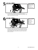
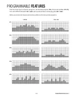
1. Insert the Console Assembly (52) into the Upright Tubes (4 & 5) and
attach with four Button Head Socket Bolts (139) and four Split Washers (113).
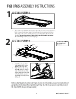
Tighten using the M6 Allen Wrench (132).
ASSEMBLY STEP 5
5
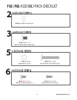
HARDWARE STEP 5
#139. 3/8”x 1-3/4”
Button Head Socket
Bolts (4 pcs)
#113. Ø 10mm
Split Washers (4 pcs)
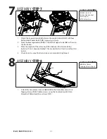
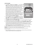
1. Attach the Left and Right Side Caps to the top of the Upright Tubes (4 & 5)
and Console Assembly Support Tubes, with eight Phillips Head Screws (140)
and four Sheet Metal Screws (119). Tighten with the Combination M5 Allen
Wrench & Phillips Head Screw Driver (131).
See illustration to determine the
ASSEMBLY STEP 6
6
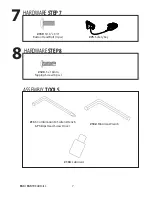
HARDWARE STEP 6
#140.
M5x15
mm
Phillips Head
Screws (8 pcs)
#119. 3.5x12mm
Sheet Metal
Screws (4 pcs)
F63 / F65 TREADMILL
Summary of Contents for F63
Page 40: ...38 EXPLODED DIAGRAM F65 ...
Page 46: ...44 EXPLODED DIAGRAM F63 ...


