Dyaco Canada Inc. 2013
12
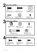
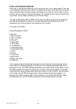
#75
. Switch Wire Cap
(2 pcs)
#157
. 3/8” x 7T
Nyloc Nut (6 pcs)
#164
. 3/8” x 19 x 1.5T
Flat Washer (8 pcs)
#181
. 3/8” x 23 x 2T
Curved Washer (4 pcs)
#206
. 3/8” x 2-1/4” Hex
Head Bolt (6 pcs)
#139
. M5 x 15mm
Phillips Head Screw
(29 pcs)
#142
. Ø 3.5 x 12mm Sheet
Metal Screw (18 pcs)
#145
. M6 x 10mm
Phillips Head Screw
(4 pcs)
ASSEMBLY INSTRUCTIONS
3
UPPER
HANDLE BAR ARMS
HARDWARE
STEP 3
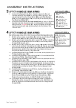
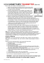
1. Connect the Swing Arm (
L-10
) to the left Lower arm (
13
) and
connect the Swing Arm (
R-11
) to the right Lower arm (
14
) , and
secure them with six Hex Head Bolts (
206
), eight Flat Washers
(
164
), four Curved Washers (
181
) and six Nyloc Nuts (
157
) using
the Wrenches (
184
&
187
).
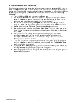
2. Connect the two wires (
L-61
to
62
&
R-60
to
62
) on the L & R sides
together and store the excess wire, including plastic connectors,
back inside the
console
mast (
12
). Place the rubber grommets (
75
)
over the wire on each side and snap them into the holes of the
console mast.
4
UPPER
HANDLE BAR ARMS
HARDWARE
STEP 4
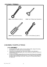
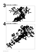
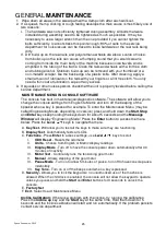
Use either screw driver (185 or 186) to secure the following plastic parts.
1. Match up the console covers (
94
&
95
) and secure with three Phillips
head screws (
139
) and two sheet metal screws (
142
).
2. Match up the Inner Connecting Arm Covers (
111
&
112
). Install the
covers with two Sheet Metal Screws (
142
) and two Phillips Head
Screws (
139
) to each joint.
3. Match up the outer Connecting Arm Covers (
109
&
110
) and install
onto the Left and Right Connecting Arms (
8
&
9
). Secure each side
with a Phillips Head Screw (
139
) and two Sheet Metal Screws (
142
).
Make sure you position the covers with the arrows pointing up. If
they are installed incorrectly, they will break.
4. Install Sliding Wheel Covers (
104
) on each side and secure with four
Phillips Head Screws (
139
).
5. Install the two Stabilizer Covers (
117
&
118
) on the middle stabilizer
bar with two Phillips Head Screws (
139
).
6. Install the Front Stabilizer Cover (
103
) on the front stabilizer with two
Phillips Head Screws (
139
).
7. Install the two incline Cover brackets (
25
), with the hole for mounting
the plastic cover on the bent tab facing rearward, and secure them
on the Incline Rail Assembly (
2
) with four Phillips Head Screws (
145
).
Install the Rear incline bar cover (
115
) on the rail base with two
Screws (
139
).
8. Install the Rear Stabilizer Cover (
116
) on the Rear Stabilizer with
four Phillips Head Screws (
139
).
9. Mate the Front Handle Bar Cover (
L-105
) and the Rear Handle Bar
Cover (
L-106
) together on the Left Arm and secure with four Sheet
Metal Screws (
142
)using the Phillips Head Screw Driver (
186
).
Repeat the same procedure for #’s
107
&
108
on the right side.
10. This step to be performed after the elliptical power is plugged in.
Elevate the incline to Level 8 and install the incline Rail front cover
(
113
) up against the middle stabilizer tube with four Phillips Head
Screws (
139
).


