Solaronics SSTG Installation, Operation & Maintenance Instructions Manual Download Page 17

17

TROUBLESHOOTING


Check for symptoms and possible causes in the order presented from the top of this chart to the bottom.


The symptoms and possible causes are in a logical progressive order as in a flow chart.
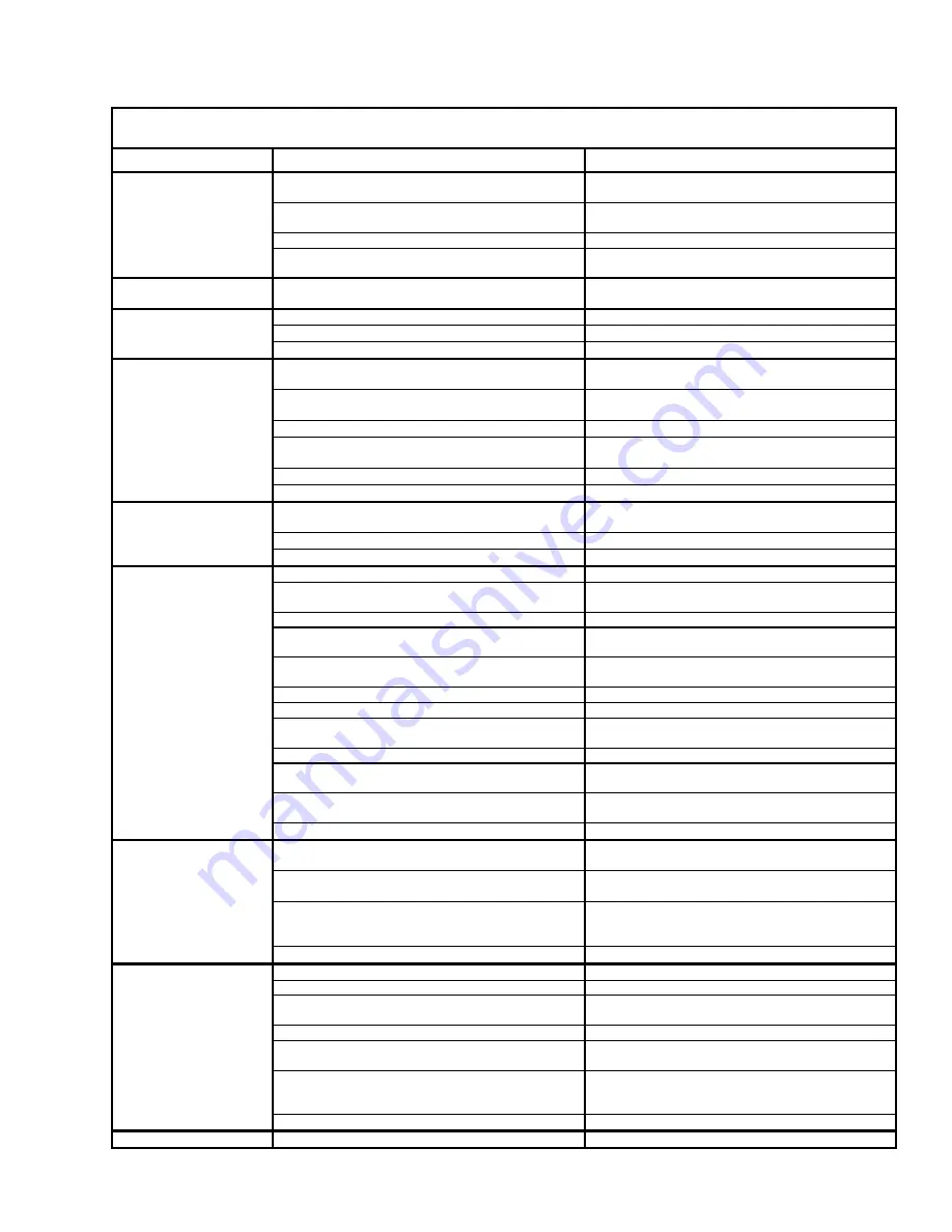
SYMPTOM

POSSIBLE CAUSE

CORRECTIVE ACTION

1. 

Heaters not isolated during high pressure leak
testing.

1. 

Replace combination gas valves on each
heater.

2. 

All gas lines not completely bled of air.

2. 

Disconnect flex hose at each heater until gas is
present.  Connect flex hose and leak test.

3. 

Gas supply regulator reversed.

3. 

Remove and install properly.

New installation.

4. 

Electrical supply line voltage & neutral polarity
reversed.

4. 

Correct electrical supply polarity.

Gas odor.

1. 

Gas pipe joints loose.

1. 

Check joints with soap solution, tighten as
needed.

1. 

Power supply fuse defective.

1. 

Replace fuse.

2. 

115 VAC not reaching heater.

2. 

Check thermostat and wiring and fix.

Blower / PL-1 light does
not come on when
system energized.

3. 

Blower defective.

3. 

Replace blower.

1. 

Inlet or exhaust piping not the proper size and
length.  (Refer to manual.)

1. 

Replace piping as required.

2. 

Inlet or exhaust termination fittings not to factory
specifications.

2. 

Replace fittings as required.

3. 

Inlet or exhaust blocked.

3. 

Clear blockage.

4. 

Airflow tubing or snubber orifice blocked in one
or both tubes.

4. 

Clear blockage.

5. 

Blower wheel dirty or damaged.

5. 

Clean or repair wheel.

Pressure switch does
not close / PL-2 light
does not come on.

6. 

Airflow pressure switch defective.

6. 

Replace airflow pressure switch.

1. 

115 VAC not reaching the Ignition Detection
Control (IDC) due to loose wire or connector.

1. 

Repair loose wire or connector.

2. 

High-voltage wire loose or damaged.

2. 

Secure high-voltage wire or replace ignitor.

Ignitor does not spark /
PL-3 light does not
come on.

3. 

Ignition Detection Control (IDC) defective.

3. 

Replace IDC box.

1. 

Gas supply not turned on.

1. 

Open all manual gas supply valves.

2. 

Ignitor not sparking at the tips.

2. 

Measure spark gap and adjust gap as
necessary to 5/32" [0.156" (3.96mm)].

3. 

Ignitor not sparking at correct gap.

3. 

Replace ignitor.

4. 

Gas inlet pressure not correct.  (See serial
plate).  Gas inlet piping not sized correctly.

4. 

Replace inlet gas piping with correct size pipe.

5. 

Gas inlet pressure not correct.  (See serial
plate).  Gas supply regulator not set correctly.

5. 

Adjust gas supply regulator to set inlet pressure
to proper level.  (See serial plate).

6. 

Gas supply regulator sticking.

6. 

Replace gas supply regulator.

7. 

Combination gas valve not in the ON position.

7. 

Turn combination gas valve to the ON position.

8. 

Ignition Detection Control (IDC) not sending
115VAC to combination gas valve.

8. 

Replace IDC box.

9. 

Combination gas valve defective.

9. 

Replace combination gas valve.

10.  Combination gas valve outlet (manifold)

pressure not correct.  (See serial plate).

10.  Adjust combination gas valve regulator to set

inlet (manifold) pressure to proper level.

11.  Main or sub gas orifice blocked by spider web,

etc.

11.  Clear blockage.

Burner does not ignite.
(There are three trials-
for-ignition before the
IDC goes into lockout).

12.  Gas orifice(s) or air orifice size not correct.

12.  Install correct size gas orifice(s) or air orifice.

1. 

Power supply not grounded to a true earth
ground.

1. 

Install a true earth ground to the power supply.

2. 

Flame sensor wire loose or damaged.

2. 

Secure flame sensor wire or replace wire
harness to IDC box.

3. 

Flame signal not at least -17 VDC.

3. 

Check gas inlet and manifold pressures
compared to the possible causes in the previous
symptom where the burner does not ignite.

Spark does not stop
when the burner ignites.

4. 

Ignition Detection Control (IDC) is defective.

4. 

Replace IDC box.

1. 

Flame sensor wire is loose or damaged.

1. 

Replace wire harness to IDC box.

2. 

Ground connection to IDC loose.

2. 

Tighten ground connection to IDC.

3. 

Electrical supply line voltage & neutral polarity
reversed.

3. 

Correct electrical supply polarity.

4. 

Inlet or exhaust partially blocked.

4. 

Clear blockage.

5. 

Airflow pressure switch erratic or defective.

5. 

Consult factory or replace airflow pressure
switch.

6. 

Flame signal not at least -17 VDC.

6. 

Check gas inlet and manifold pressures
compared to the possible causes in the previous
symptom where the burner does not ignite.

Burner does not stay lit
until the thermostat is
satisfied.

7. 

Ignition Detection Control (IDC) defective.

7. 

Replace IDC box.

Heater will not turn off.

1. 

Thermostat defective.

1. 

Replace thermostat.

Summary of Contents for SSTG

Page 1: ...damage personal injury and or death A gas fired appliance could expose you to substances in fuel or from fuel combustion which have been determined by the State of California to cause cancer birth de...

Page 2: ...ached This will cause damage to the controls within the burner requiring them to be replaced If heater is being operated in an atmosphere with a negative pressure or an atmosphere containing contamina...

Page 3: ...gth of air supply pipe air supply cap specifications and indoor air supply 10 EXHAUST VENTING outdoor exhaust venting maximum length of exhaust vent pipe vent cap specifications and unvented indoor ve...

Page 4: ...installation must meet the requirements of the Occupational Safety and Health Act OSHA which requires OSHA approved service and safety access to the systems after they are installed AIRCRAFT HANGARS...

Page 5: ...Burning Equipment CAN CSA C22 2 No 3 Vent terminal clearances shall be in accordance with the current Canadian Natural Gas and Propane Installation Code CAN CSA B149 1 A horizontal vent shall not term...

Page 6: ...ch may be damaged by temperatures 90 F above 50 C above ambient room temperature These clearances to combustibles are specified on each heater s serial plate In locations used for the storage of combu...

Page 7: ...9 8 2 4 1 0 3 13 5 4 1 11 5 3 5 6 1 8 1 0 3 90 27 4 90 95 26 28 12 0 3 7 10 0 3 0 8 2 4 1 0 3 14 0 4 3 12 0 3 7 6 1 8 1 0 3 95 29 0 100 105 29 31 12 5 3 8 10 5 3 2 8 2 4 1 0 3 14 5 4 4 12 5 3 8 6 1 8...

Page 8: ...EAR FT 10 7 M FOR 40 TO 125 MBTUH 12 37 KW OR 40 LINEAR FT 12 2 M FOR 130 TO 200 MBTUH 38 59KW NO MORE THAN TWO 90 ELBOWS MAY BE USED A 90 ELBOW IS EQUIVALENT TO 10 LINEAR FT 3 0 M INLET AIR SLEEVE SE...

Page 9: ...NGTH OF PIPING FOR ALL INDOOR JOINTS USE RTV SEALANT TO PREVENT HOT FLUE GAS LEAKAGE INTO THE BUILDING USE A SHEET METAL PIPE AND CRIMPER FOR JOINING IDENTICAL SIZE SHEET METAL PIPES USE THREE 3 6 SHE...

Page 10: ...igh humidity areas combustion air must come from outdoors Outdoor air supply may be accomplished by bringing in air through piping from either the roof or wall as the drawings illustrate When combusti...

Page 11: ...s limited to appliances with neutral or negative pressures Local authorities may waive this provision since the heaters are approved for indoor venting with proper exhaust and leakage due to condensat...

Page 12: ...ired correctly Electrical power takeoff must be connected to a separately fused circuit with a disconnect and must be properly polarized and grounded to the heaters power cord Do not run wiring over t...

Page 13: ...s valve steps up to its operating position DC electrical current flows from sensing electrode through flame to ground IDC senses flame presence turns OFF spark gas continues flowing through valve Vali...

Page 14: ...15 2 m 2 1 in 53 mm 25 30 ft 7 6 9 1 m 1 5 in 38 mm 55 60 ft 16 8 18 3 m 2 4 in 61 mm 35 40 ft 10 7 12 2 m 1 8 in 46 mm 65 70 ft 19 9 21 3 2 7 in 67 mm When inlet gas pressure is greater than 14 in WC...

Page 15: ...nd the manifold gas pressure For proper sequence of operation see the OPERATION AND SHUTDOWN section If heater does not operate normally see the TROUBLESHOOTING section Once startup testing is complet...

Page 16: ...speed Remove the cover by removing the 4 sheet metal screws on top of the cover Remove the ignitor by removing ONLY the end where the vinyl tubing is attached to the ignitor bracket the fitting to wh...

Page 17: ...serial plate Gas inlet piping not sized correctly 4 Replace inlet gas piping with correct size pipe 5 Gas inlet pressure not correct See serial plate Gas supply regulator not set correctly 5 Adjust g...

Page 18: ...sembly with snubber and fittings 14 Strain relief bushing 4 Burner core 15 System validation light 5 Ignitor gasket 16 Ignition detection control IDC 6 Ignitor 17 Burner tube holding bracket with scre...

Page 19: ...ING DOCK AIRPLANE HANGAR DOORS OR OTHER WINDY AREAS FASTEN THE REFLECTORS TO THE REFLECTOR SUPPORT BRACKETS WITH TEK SCREWS OR OTHER POSITIVE MEANS BRACKET TEK SCREW REFLECTOR BRACKET REFLECTOR BURNER...

Page 20: ...with its radiant tubes horizontal or with the heat exchanger angled above the combustion chamber as illustrated by the drawing below When radiant tubes are horizontal reflectors may be individually r...

Page 21: ...m Each system can use a maximum of two 2 16 gauge 17 cm stainless steel or aluminized steel 90 elbows OR one 1 16 gauge 17 cm stainless steel or aluminized steel 180 U bend Elbows and U bends can not...

Page 22: ...22 THIS PAGE INTENTIONALLY LEFT BLANK...

Page 23: ...H5 130 150 38 44 45 13 7 C N L 4 C2 H2 H2 H6 H5 100 29 50 15 2 B N L 4 C2 C3 H2 H2 H2 H5 105 120 31 35 50 15 2 B N L 4 C2 H2 H2 H6 H5 125 37 50 15 2 B N only 4 C2 H2 H2 H6 H5 125 37 50 15 2 C L only 4...

Page 24: ...ed on tube EXHAUST END stenciled on tube white tape at exhaust end 2 two stainless steel 304 tube clamps 10 ft 3m stainless steel 304 reflector 2 stainless steel 304 reflector brackets 10 ft 3m 16 ga...

Page 25: ...d 9 1 10 7 m MC 10 ft 3m 16 ga 1 7mm 304L stainless steel tube painted black Stainless steel 304 tube clamp 10 ft 3m stainless steel 304 reflector 2 stainless steel 304 reflector brackets 10 ft 3m 16...

Page 26: ...he S hook into the loop in the sliding hanger at the top of the tube clamp crimping it closed and then inserting the other end of the S hook into the last chain link and crimping it closed NOTE Make s...

Page 27: ...edge of the reflector under the reflector bracket tab Be certain the spring steel clamp is in place to hold the reflector securely as shown If the reflectors are to be at an angle loosen the two 2 nu...

Page 28: ..._____ THIRD Contact the Nearest Distributor Name _________________________________________________________ Address _______________________________________________________ _____________________________...

Reviews: