For further assistance, please contact technical dispenser support at (920) 940-8904
V
I
.
SWITCH CONTROL SETTINGS
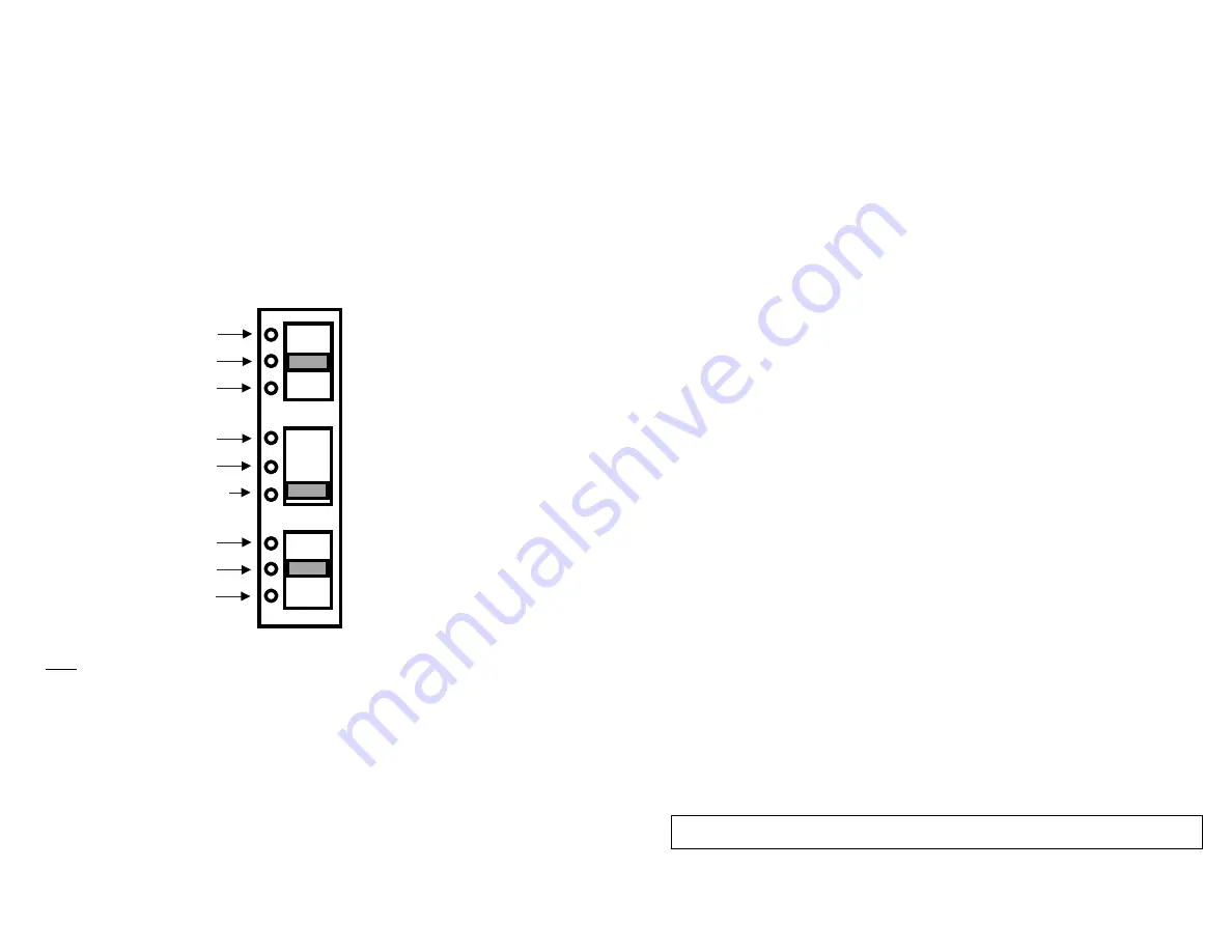
There are three switches
available
to customize the control system. These
switches are inside, to the back-right corner of the dispenser
(see Figure
11).
Switch# 1 is designed for paper saving method. Using this method, any dispense
that occurs within 3 seconds of the previous dispense will result in a sheet that is
shorter
(paper saving)
than the initial dispense.
Switch# 2 is designed to control the delay-time between two dispense actuations.
Switch# 3 is designed to control the sheet length of each regular dispense.
Switch# 1
:
Paper Saving Mode
Switch#
2
:
Dispensing Delay
Switch#
3
:
Paper
Length
12.5% Saving
0% Saving
25% Saving
Approximately 2 seconds
Approximately 1 seconds
Approximately 1/2 seconds
Long
Medium
Short
V
I
I
.
LED INDICATOR LIGHT FUNCTION
The LED indicator light located at the right top corner of the opening where the
paper is dispensed.
If using batteries, the LED light will flash one time after the batteries are installed
correctly to indicate that the unit is powered up. The LED light will also flash
once after every dispense
to i
ndicate the unit is ready for the next use. When the
batteries need replacement, the
LED l
ight will flash every 1.5 seconds.
1. If the LED is flashing, batteries may need to be replaced (if using batteries).
2. If the LED is not flashing, make sure batteries are present and loaded in
the correct orientation. If using Power Converter Plug, check the plug-
connections.
3. Open the cover:
a. Make sure paper is loaded correctly, on the correct roll holders.
b. Make sure paper is not jammed, paper roll turns freely and the
paper path is clear of obstructions.
877
7
002
Released
February
22
201
9
10
If using Power Converter Plug, the LED light will flash every 1.5 seconds to indicate
that the plug is conn
ect
ed to the power supply.
V
II
I
.
STUB-ROLL TRANSFER LOADING
When the paper roll gets down to 3-inch in diameter or smaller, the roll can be
transfered to the stub-roll holders in the lower, rear section of the dispenser.
Place
the paper "tail"
underneath the Stub-Roll Monitor
so that paper from the
s
tub-
r
oll can be used up first.
Install a new full roll of paper in the upper roll holders. Pl
ace
the new paper
"tail" on top of the
Stub-Roll Monitor
and under the
Transfer Arm as showed
in
the
"
Stub-Roll Transfering
" instruction graphic inside the cover. Paper from
the new roll will automatically engage and feed out of the dispenser when the
stub-roll paper runs out.
I
X
.
FAILURE DIAGNO
S
TICS
If the unit is not dispense:
Note: When the Paper Saving Mode is activated (switch# 1 is positioning at
12.5% or 25% saving), the system will overide the time-delay setting, which
means the delay time will always be 1/2 seconds between every dispense.


