9
Safety, Installation, and Operations Manual
© Solaria Corporation All rights reserved. Contents subject to change without notice. SOL-MAN-0002 Rev 09,12-2020
Power Unlocked by Design
PowerXT xxxR-PD
y
Mounting Using Clamps:
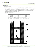
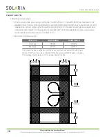
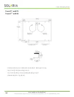
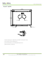
When using clamps, place clamps within the “CLAMP AREA A” or “CLAMP AREA B” as indicated on the
diagram below. Follow clamp manufacturer’s recommended hardware and torque requirements for solar
installations. Various clamp systems specifically designed for PV module mountings are available and
compatible with PowerXT. In the absence of manufacturer’s recommendations for clamp size, Solaria
recommends minimum clamp size of 40mm (1.57”).
Maximum Allowed Loading:
TEST LOAD
CLAMP AREA A
CLAMP AREA B
Front Load
5400Pa
2400Pa
Rear Load
3600Pa
2400Pa
The module has been qualified to meet the heavy snow load requirement of 5400Pa (per
IEC61215-2005), for test loads of 5400Pa (Front, 3rd cycle) and 3600Pa (Back, 3rd cycle).
This includes a safety factor of 1.5 for a design load of 1600Pa.
11in
279mm
11in
279mm
11in
279mm
CLAMP AREA B
11in
279mm
CLAMP AREA B
6in
152mm
CLAMP AREA A
6in
152mm
CLAMP AREA A
D
C
B
A
A
B
C
D
1
2
3
4
5
6
7
8
8
7
6
5
4
3
2
1
E
F
E
F
REV
D
04
04
6200 Paseo Padre Parkway,
Fremont, CA 94555
+1 510 270 2500
www.solaria.com
SHEET 2 OF 2
UNLESS OTHERWISE SPECIFIED:
SCALE: 1:10
WEIGHT: kg
REV
DRAWING NUMBER
D
SIZE
DESCRIPTION
NAME
DATE
THIRD ANGLE PROJECTION
ENG APPR.
DRAWN
FINISH
MATERIAL
INTERPRET DRAWING
PER ASME Y14.100-2004
INTERPRET GEOMETRIC
TOLERANCING PER ASME Y14.5M-1994
DO NOT SCALE DRAWING
DIMENSIONS ARE IN MM [IN]
TOLERANCES:
ANGULAR: 0.5
LINEAR X 0.50
LINEAR .X 0.25
LINEAR .XX 0.13
APPLICATION
USED ON
NEXT ASSY
PROPRIETARY AND CONFIDENTIAL
THE INFORMATION CONTAINED IN THIS
DRAWING IS THE SOLE PROPERTY OF
SOLARIA CORPORATION. ANY
REPRODUCTION IN PART OR AS A WHOLE
WITHOUT THE WRITTEN PERMISSION OF
SOLARIA CORPORATION IS PROHIBITED.


