SolarEdge SMI-180 Installation Manual Download Page 68

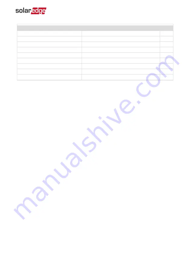
Installation Specifications
Dimensions (W x D x H)

317 x 214 x 540 / 12.5 x 8.4 x 21 

mm/in

Weight 

25 / 55 

kg/ lb

Operating Temperature Range

-20 to +60 / -4 to +140

°C/°F

Protection Rating

IP66


Relative Humidity

0 to 100 

%

Input Wiring Gauge

35 to 105 

mm

2

Output Wiring Gauge

35 to 105

mm

2

Storage Temperature Range

-40 to +85 / -40 to +185  

°C/°F

Storage Humidity Range

0 to 95 

%

Appendix B: SMI Specifications     

66

SMI-180 Installation Guide MAN-01-00157-1.1

Summary of Contents for SMI-180

Page 1: ...Installation Guide Safety and Monitoring Interface SMI 180 For Europe and APAC Version 1 1 ...

Page 2: ... necessary However discrepancies cannot be excluded No guarantee is made for the completeness of these documents The images contained in this document are for illustrative purposes only and may vary depending on product models Emission Compliance This equipment has been tested and found to comply with the limits applied by the local regulations These limits are designed to provide reasonable prote...

Page 3: ...er is connected Consult the dealer or an experienced radio TV technician for help Changes or modifications not expressly approved by the party responsible for compliance may void the user s authority to operate the equipment SMI 180 Installation Guide MAN 01 00157 1 1 2 Emission Compliance ...

Page 4: ... of Ireland 353 1800 901 575 support uk solaredge com United Kingdom 44 0800 028 1183 US Canada 1 510 498 3200 ussupport solaredge com Greece 49 89 454 59730 support solaredge com Israel 972 073 240 3122 Middle East Africa 972 073 240 3118 South Africa 27 0800 982 659 Turkey 90 216 706 1929 Worldwide 972 073 240 3118 Before contact make sure to have the following information at hand Model and seri...

Page 5: ... 21 Step 1 Activating the System 21 Step 2 Pairing Power Optimizers to the SMI 22 Step 3 Verifying Proper Activation 23 Step 4 Reporting and Monitoring Installation Data 24 Chapter 4 SMI Connections 27 Connecting the DC Out Cables to the SMI 27 Connecting the Inverter to the SMI 28 Verifying Proper Operation 29 Chapter 5 User Interface 30 LCD User Buttons 30 SMI Configuration Setup Mode 31 Configu...

Page 6: ... Communication 58 Troubleshooting SolarEdge Systems Addendum Europe APAC 60 Error Codes 60 Appendix B SMI Specifications 63 Mechanical Specifications 63 Technical Specifications 65 Support and Contact Information 5 SMI 180 Installation Guide MAN 01 00157 1 1 ...

Page 7: ...TION Denotes a hazard It calls attention to a procedure that if not correctly performed or adhered to could result in damage or destruction of the product Do not proceed beyond a caution sign until the indicated conditions are fully understood and met NOTE Denotes additional information about the current subject IMPORTANT SAFETY FEATURE Denotes information about safety issues Disposal requirements...

Page 8: ... light it supplies DC voltage to the power optimizers CAUTION This unit must be operated under the specified operating conditions as described in the Technical Specifications or the latest technical specification datasheet available on the SolarEdge website at http www solaredge com groups products overview NOTE The following warning symbols appear on the SMI warning label Risk of electric shock R...

Page 9: ...e above The SMI supports the SolarEdge optimizer SafeDC feature The SafeDC mechanism automatically shuts down module voltage whenever the grid power is shut down thus providing greater safety during installation maintenance and firefighting The SMI is installed between the SolarEdge power optimizers and a non SolarEdge inverter and is compatible with any on grid inverter Figure 1 The SolarEdge saf...

Page 10: ... Up Communication to the Monitoring Platform on page 44 Power Supply Input Used to connect the SMI to an auxiliary power supply unit LCD Panel displays SMI information and configuration parameters LCD LEDs Three LEDs indicate the following SMI statuses Color Description Functionality Green Power OK Indicates whether the SMI is connected to power Yellow Module Communication Blinking when monitoring...

Page 11: ...ge 3 Open the cover s six Allen screws and carefully remove the cover CAUTION When removing the cover make sure not to damage internal components SolarEdge will not be held responsible for any components damaged as a result of incautious cover removal To close the SMI cover Attach the cover and secure it by tightening the screws with a torque of 4 0 N m 2 9 lb ft For proper sealing first tighten t...

Page 12: ...ment includes the DC input and output connections The lower compartment is accessed by lifting the plate which is hinged to the SMI enclosure To access the lower compartment 1 Loosen the two screws on the left side of the internal plate 2 Carefully lift the internal plate Figure 5 Accessing the SMI lower compartment Chapter 1 Introducing the SMI 180 Safety and Monitoring Interface for Large Scale ...

Page 13: ...bracket AC ferrite bead kit Identifying the SMI Refer to the sticker on the SMI that specifies its Serial Number and its Electrical Ratings Provide the serial number when contacting SolarEdge support The serial number is also required when opening a new site in the monitoring platform Installation Workflow 1 Mounting the SMI page 12 2 Accessing the Internal Compartments page 10 3 Connecting PV Str...

Page 14: ... SMI mounting location on a wall or pole as follows To allow proper heat dissipation maintain 2 5 cm minimum clearance areas between the SMI and other objects Make sure the mounting surface or structure can support the weight of the SMI 2 Position the mounting bracket against the wall and mark the drilling hole locations Ensure that the flat side of the bracket is at the bottom Figure 6 Wall mount...

Page 15: ...lb ft Figure 8 Inserting the bracket screw To mount the SMI horizontally 1 Determine the SMI mounting location on a rail or on the floor as follows To allow proper heat dissipation maintain 2 5 cm minimum clearance areas between the SMI and other objects Make sure the mounting surface or structure can support the weight of the SMI SMI 180 Installation Guide MAN 01 00157 1 1 13 Mounting the SMI ...

Page 16: ... Horizontal mounting brackets 4 Mount the unit on the rail or structure Use 5 16 screws or bolts 8 0 mm diameter for anchoring to the surface Figure 11 Horizontal anchoring screws Functional earthling is required to enable the over voltage protection To earth the SMI connect a grounding cable to the grounding location at the rear of the SMI The grounding cable must be at least 1 5mm2 You may use a...

Page 17: ...ure describes how to connect the DC cables from the power optimizer strings to the SMI A typical installation has up to 18 strings connected to an SMI through a combiner box Figure 13 String connection SMI 180 Installation Guide MAN 01 00157 1 1 15 Connecting PV Strings to the SMI ...

Page 18: ...partments on page 10 Figure 14 Connection area 2 Use an Allen key to loosen the 5 16 screws of the SMI DC power distribution blocks 3 Remove the seal from the glands labeled DC IN DC IN Figure 15 SMI bottom view 4 If the cables from the combiner box are 18 25 mm in diameter insert the wires through the opening If the cables are less than 18 mm in diameter replace the rubber seals in the gland with...

Page 19: ...regulations require using cable lugs use the lugs and screws supplied in the package Fasten the cable ring terminal to the lug apply torque 17 N m 12 5 Lb ft and insert the lug into the input terminal blocks Figure 16 Using cable lugs 6 Fasten the Allen screws of the power distribution blocks Apply a torque of 30 N m 22 lb ft Figure 17 DC IN cables connected 7 Seal all glands SMI 180 Installation ...

Page 20: ...unding Figure 18 Example Grounding locations Connecting to a DC Power Supply The SMI is powered from a separate DC power supply unit PSU not provided by SolarEdge Use a PSU with 48V nominal voltage The input of the SMI can be connected to voltages 30 55 VDC and each SMI will consume 12W CAUTION The PSU must be limited or fused to 50A Up to 10 SMIs can connect to a single PSU Refer to the following...

Page 21: ...8 14 2 08 720 2362 18 0 82 280 918 20 0 52 180 590 6 14 2 08 960 3150 18 0 82 380 1246 20 0 52 240 787 4 14 2 08 1440 4724 18 0 82 570 1870 20 0 52 360 1181 2 14 2 08 2890 9481 18 0 82 1140 3740 20 0 52 720 2362 Figure 19 Power supply connection SMI 180 Installation Guide MAN 01 00157 1 1 19 Connecting to a DC Power Supply ...

Page 22: ...he SMI 3 Loosen the screws of the pins on the leftmost and rightmost of the 4 pin connector supplied in the SMI package If connecting more than one SMI loosen all four screws 4 Connect the wire s to the left side of the connector 5 Connect the wire s to the right side of the connector 6 Push the connector into the 4 pin terminal block on the communication board Figure 21 4 pin connector and power ...

Page 23: ...ears only upon first telemetry reception from the power optimizers Indicates the number of power optimizers that have been paired to this SMI Vdc V The DC input voltage of the longest string connected to the SMI There should be a safety voltage of 1V for each power optimizer in the string NOTE A measurement error on the SMI LCD of 3 V is acceptable Idc A If the current sensor option is set display...

Page 24: ...re disconnected otherwise the following error is displayed and the pairing process halts D i s c o n n e c t O u t p u t 1 Perform pairing Press and hold down the SMI LCD Light button for about 10 seconds The following message is displayed K e e p h o l d i n g b u t t o n f o r p a i r i n g r e l e a s e t o e n t e r m e n u R e m a i n i n g 3 s e c Keep holding for 5 seconds until the followi...

Page 25: ...t to MaxVout mode The detection and assignment of power optimizers may take up to 2 minutes The system startup process begins Since the SMI is ON the power optimizers start producing power WARNING When you turn ON the SMI ON OFF switch the DC cables carry a high voltage and the power optimizers no longer output a safe 1V output Step 3 Verifying Proper Activation After pairing a status screen simil...

Page 26: ...surance through immediate fault detection and alerts at the module string and system level Using the platform you can View the latest performance of specific components Find under performing components such as modules by comparing their performance to that of other components of the same type Pinpoint the location of alerted components using the physical layout The monitoring platform enables acce...

Page 27: ...you need to map the locations of the installed power optimizers To map the locations use one of the methods described in the next sections Designer Designer recommends inverter and power optimizer selection per site size and enables report generation You can create a project in Designer and export the site design with the string layout to the monitoring platform For more information refer to https...

Page 28: ...e pdf using the detachable 2D barcode stickers on each power optimizer Once the form is completed use the Mapper to scan the 2D codes and create the map in the monitoring platform Optionally you can send the sticker sheet to SolarEdge Support for physical layout creation Chapter 3 Commissioning the Installation 26 SMI 180 Installation Guide MAN 01 00157 1 1 ...

Page 29: ... until at least five minutes have passed Doing so may cause injury or loss of life damage to the device and or danger of fire 2 Turn OFF the PSU 3 Switch the AC to the inverter OFF as described in its manual If applicable turn the inverter DC Safety Switch to OFF 4 Open the lower compartment of the SMI as described in Accessing the Internal Compartments on page 10 5 Use a 5 16 Allen key to loosen ...

Page 30: ...ribed in Step 2 Pairing Power Optimizers to the SMI on page 22 2 Connect the SMI DC and DC output wires to the input of the inverter CAUTION Complete the pairing procedure before connecting the DC output of the SMI to the inverter Do not perform pairing when the DC output of the SMI is connected to the inverter 3 Switch the AC to the inverter ON as described in its manual If applicable turn the in...

Page 31: ...he power optimizers and at least one power optimizer is sending monitoring data Vdc v Specifies the DC input voltage which should be within the DC voltage operating range of the SMI Idc A The DC input current Pdc w Specifies the expected DC output power 2 Take note of the serial on the SMI label This information is used in the SolarEdge monitoring platform to identify this SMI and is needed when o...

Page 32: ...lied is displayed The LCD screen displays status information of the system and various menus for configuration options The LCD panel and buttons are used during the following processes Operational mode The LCD panel allows checking for proper system operation Refer to Status Screens Operational Mode on page 39 for a description of this option Use the LCD light button to toggle through the informat...

Page 33: ... in its manual 2 Turn the SMI ON OFF switch to OFF Wait until the voltage is safe 50V WARNING Do not touch the DC power connections until the DC voltage is at a safe level Doing so may cause injury or loss of life damage to the device and or danger of fire 3 Press the Enter button for at least 5 seconds The following message is displayed P l e a s e e n t e r P a s s w o r d 4 Use the three rightm...

Page 34: ...e n c h I t a l i a n Communication 1 S e r v e r L A N L A N C o n f R S 4 8 5 1 C o n f S Z i g B e e C o n f S W i F i C o n f N A C e l l u l a r C o n f S l a v e D e t e c t 1 If ZigBee is connected the Wi Fi Conf menu is not displayed If ZigBee is not connected ZigBee Conf and Wi Fi Conf are both displayed with N A Chapter 5 User Interface 32 SMI 180 Installation Guide MAN 01 00157 1 1 Disp...

Page 35: ... the following message is displayed K e e p h o l d i n g b u t t o n f o r p a i r i n g r e l e a s e t o e n t e r m e n u R e m a i n i n g 3 s e c Releasing the button displays the following menu O p t i m i z e r p a i r i n g L a n g u a g e e n g C o m m u n i c a t i o n M a i n t e n a n c e I n f o r m a t i o n E x i t 3 Short press one second to scroll down to the next menu option and...

Page 36: ...A N C o n f R S 4 8 5 1 C o n f S R S 4 8 5 2 C o n f S Z i g B e e C o n f S W i F i C o n f N A R S 2 3 2 C o n f C e l l u l a r C o n f S l a v e D e t e c t E x i t Information E r r o r L o g W a r n i n g l o g E x i t Maintenance D a t e a n d T i m e R e s e t C o u n t e r s F a c t o r y R e s e t S W U p g r a d e S D C a r d E x i t The options presented in these menus are described i...

Page 37: ...Communication option to define and configure The communication option used by the SMI to communicate with the SolarEdge monitoring platform The communication option used to communicate between multiple SolarEdge devices or other external non SolarEdge devices such as energy meters or loggers NOTE The Server menu shows only the communication options installed in the SMI The following shows a hierar...

Page 38: ... e r v e r P o r t M o d b u s T C P D i s RS485 X Conf D e v i c e T y p e S E P r o t o c o l M D e v i c e I D 1 S l a v e D e t e c t C l u s t e r S L V D e t e c t L o n g S l a v e D e t e c t S l a v e L i s t M u l t i I n v S e t 1 If ZigBee is connected the Wi Fi Conf menu is not displayed If ZigBee is not connected ZigBee Conf and Wi Fi Conf are both displayed with N A and their menus ...

Page 39: ...e v i c e T y p e R R C R Display Select Display to set the following L C D O n T i m e 3 0 LCD On Time 30 The number of seconds that the LCD backlight is ON after pressing the LCD light button Set a value within the range of 10 120 seconds Maintenance Select Maintenance to set the following options D a t e a n d T i m e R e s e t C o u n t e r s F a c t o r y R e s e t F W U p g r a d e 1 When us...

Page 40: ...ease have these numbers ready when you contact SolarEdge Support Error Log Displays the last five errors Warning Log Displays the last five warnings Hardware IDs Displays the following HW serial numbers if exist and connected to the inverter ID the inverter s ID RGM1 Revenue Grade Meter Energy Meter with Modbus Connection RGM2 A second external Energy Meter with Modbus Connection ZB ZigBee MAC add...

Page 41: ...zers identified during the most recent pairing process If XXX and YYY are not equal there may be a problem in one or more power optimizers S_OK The connection to the SolarEdge monitoring platform is successful ON OFF Indicates the position of the SMI ON OFF switch SMI 180 Installation Guide MAN 01 00157 1 1 39 Status Screens Operational Mode Telemetry Status This screen displays the last power opt...

Page 42: ...ubleshoot them refer to Troubleshooting Communication on page 58 For a list of the possible errors and how to troubleshoot them refer to Errors and Troubleshooting on page 58 Error message according to failure Refer to http www solaredge com sites default files se inverter installation guide error codes pdf Chapter 5 User Interface 40 SMI 180 Installation Guide MAN 01 00157 1 1 Server Communicatio...

Page 43: ...figuration IP Mask Gateway and MAC address Media Access Control of the SMI I P 1 9 2 1 6 8 2 1 1 9 M S K 2 5 5 2 5 5 2 5 5 0 G W 1 9 2 1 6 8 2 1 M A C 0 2 7 0 2 0 0 3 9 3 6 ZigBee Status This screen describes the ZigBee configuration P A N X X X X X C H X X X X X X R S S I L M I D X X X X X X RSSI The receive signal strength indication of the closest ZigBee in the system L low M medium H high and ...

Page 44: ...M Status If a GSM Plug in is connected this screen replaces the Server status screen S e r v e r C e l l S _ O K S t a t u s O K M N O x x x x x x x S i g 5 E r r o r m e s s a g e Server The method of communication to the SolarEdge monitoring platform Should display Cell Status Displays OK if the inverter established a successful physical connection to the modem S_OK The last communication to the...

Page 45: ...h as meters and batteries HA Home automation devices for Smart Energy PROT The protocol type to which the port is set For a SolarEdge device RS485 protocol ZigBee protocol S SolarEdge slave M SolarEdge master P2P ZigBee point to point MPM ZigBee multipoint master for the ZigBee gateway or for load management by the inverter MPS ZigBee multipoint slave for a ZigBee router card For electricity meter...

Page 46: ...s offered by SolarEdge are supported Ethernet Ethernet is used for a LAN connection For connection instructions refer to RS485 RS485 is used for the connection of multiple SolarEdge devices on the same bus in a master slave configuration RS485 can also be used as an interface to external devices such as meters and third party data loggers The SMI has two RS485 physical ports with the following cap...

Page 47: ...assembled during system installation The Wi Fi Plug in kit is provided with a user manual which should be reviewed prior to connection Refer to http www solaredge com sites default files se_wifi_communication_solution_installation_ guide pdf Cellular GSM CDMA This wireless communication option purchased separately enables using a cellular connection to connect one or several devices depending on t...

Page 48: ... PG16 One small External antenna cable 2 4 mm Two large Ethernet connection CAT5 6 Cellular ZigBee Wi Fi or RS232 4 5 7 mm 2 PG13 5 All three RS485 power reduction 2 5 5 mm Figure 24 Communication Glands The communication board has a standard RJ45 terminal block for Ethernet connection and a 9 pin terminal block for RS485 connection as shown below Chapter 6 Setting Up Communication to the Monitori...

Page 49: ...sed Maximum distance between the SMI and the router 100 m 330 ft NOTE If using a cable longer than 10 m 33 ft in areas where there is a risk of induced voltage surges by lightning it is recommend to use external surge protection devices For details refer to http www solaredge com files pdfs lightning_ surge_protection pdf SMI 180 Installation Guide MAN 01 00157 1 1 47 Creating an Ethernet LAN Conn...

Page 50: ...he gland and insert the CAT5 6 cable through the gland and through the gland opening in the 5 Push the cable into the cut opening of the rubber fitting Figure 27 Rubber fitting CAT5 6 standard cables have eight wires four twisted pairs as shown in the diagram below Wire colors may differ from one cable to another You can use either wiring standard as long as both sides of the cable have the same p...

Page 51: ...r s communication board or if using a spool of cable connect as follows a Insert the cable through gland 1 b Remove the cable s external insulation using a crimping tool or cable cutter and expose eight wires c Insert the eight wires into an RJ45 connector as described in Figure 28 d Use a crimping tool to crimp the connector e Connect the Ethernet connector to the RJ45 port on the digital board 1...

Page 52: ... independently to the monitoring platform 9 The SMI is configured by default to LAN If reconfiguration is required a Make sure the ON OFF switch is OFF b Turn ON the PSU c Use the internal user buttons to configure the connection as described in Communication on page 35 Chapter 6 Setting Up Communication to the Monitoring Platform 50 SMI 180 Installation Guide MAN 01 00157 1 1 NOTE If your network...

Page 53: ...ions Cable type Min 3 wire shielded twisted pair a shielded Ethernet cable Cat5 5E STP may be used Wire cross section area 0 2 1 mm 24 18 AWG a CAT5 cable may be used Maximum nodes 32 Maximum distance between first and last devices 1 km 3300 ft This section describes how to connect the RS485 bus and how to configure the bus The following menus can be used for RS485 port configuration RS485 1 2 Con...

Page 54: ...on SE Logger Used when connecting to an external non SolarEdge logger The logger can read SolarEdge inverter data for monitoring purposes None default for RS485 2 NOTE For other supported protocols refer to http www solaredge com articles se supported devices Slave Detect Is used to initiate automatic detection of the slaves connected to the master SMI The number next to the option is the number o...

Page 55: ...ins the same color for all B pins and the same color for all G pins 5 Connect all B A and G pins in all SMIs The following figure shows this connection schema Figure 31 Example of multiple SMI units in an RS485 bus connection NOTE Do not cross connect B A and G wires Make sure you are using the same RS485 port 1 2 in all devices 6 Tighten the terminal block screws 7 Push the RS485 terminal block f...

Page 56: ...rm via one of the communication options Ethernet GSM or ZigBee To configure the RS485 communication bus By default all SolarEdge devices are pre configured as slaves on the RS485 1 port Slaves can be further configured using the RS485 1 Conf option in the Communication menu 1 Enter Setup mode as described in SMI Configuration Setup Mode on page 31 2 Select Communication è Server è RS485 1 2 Conf 1...

Page 57: ...I ON OFF switch 2 Switch the AC to the inverter ON as described in its manual If applicable turn the inverter DC Safety Switch to ON 3 Wait for the SMI to connect to the SolarEdge monitoring server This may take up to two minutes A message similar to the following appears on the LCD panel V d c v I d c a P d c w 1 4 1 P _ O K 0 1 4 0 1 4 S _ O K O F F S_OK Indicates that the connection to the Sola...

Page 58: ... è Device Type è SolarEdge RS485 Conf è Protocol è Master RS485 Conf è Slave Detect The system starts automatic detection of the slave inverters connected to the master inverter The inverter should report the correct number of slaves If it does not verify the connections and terminations 4 Verify the connection of the master to the monitoring platform as described in the next section Chapter 6 Set...

Page 59: ...platform The Wi Fi Plug in kit can be purchased separately and assembled during system installation The Wi Fi Plug in kit is provided with a user manual which should be reviewed prior to connection It is available on the SolarEdge website at http www solaredge com groups products communication under Wi Fi Creating a GSM Connection This communication option enables using a GSM connection to connect...

Page 60: ... indicates an error Bit Location Error Message Cause and Troubleshooting 1st LAN Disconnected Physical connection fault Check the cable pin out assignment and cable connection Refer to Creating an Ethernet LAN Connection on page 47 2nd DHCP Failed or Invalid DHCP Config IP settings issue Check the router and SMI configuration Consult your network IT 3rd Gateway Ping Failed Ping to router failed Ch...

Page 61: ...ntify missing slaves and troubleshoot connectivity problems Use the Long slave Detect to retry connecting to slaves Analyze the Slave List to check for missing slaves and check their connection Refer to https www solaredge com sites default files troubleshooting_ undetected_RS485_devices pdf Additional Troubleshooting 1 Check that the modem or hub router is functioning properly 2 Check that the co...

Page 62: ...D 2 E r r o r C o d e 3 x D 2 L i n e 1 L i n e 2 XXX The error number firmware version 3 18xx and before X A code indicating the source of error and the error information firmware version 3 19xx and later Line 1 2 Error description The error numbers codes may differ depending on the inverter type single phase or three phase as described in the table below For troubleshooting errors that are not l...

Page 63: ... the combiner box Verify that no PV modules are connected directly in the string without a power optimizer Re commission all SMIs in the site as described in Commissioning the Installation on page 21 17 Temperature Too High Over temperature If the fault persists Verify that proper clearance exists around the SMI Check whether the SMI is installed in an area with temperatures outside its operating ...

Page 64: ...n the initial status screen with the format Warning X For example V a c V V d c V P a c W 1 0 0 5 0 0 P _ O K X X X Y Y Y S _ O K W a r n i n g 8 O N The warning is a status screen To view the warning description press the LCD button The following is a list of system warnings Warning LCD text Comments and troubleshooting CPU v3 18xx and before CPU v3 19xx and later 1 4 6 7 8x66 8x69 8x6A 8x6F Fan ...

Page 65: ...ications Mechanical Specifications Figure 33 SMI vertical mounting front side and rear views mm in Figure 34 Vertical mounting bracket dimensions SMI 180 Installation Guide MAN 01 00157 1 1 63 Appendix B SMI Specifications ...

Page 66: ...Figure 35 SMI horizontal mounting front side and isometric views Appendix B SMI Specifications 64 SMI 180 Installation Guide MAN 01 00157 1 1 ...

Page 67: ...r External power supply Input Voltage 36 55 VDC Nominal Power Consumption 12 W String Design String Length Module Inverter Dependent Maximum Number of Input Strings using an external combiner box 24 Maximum Number of Power Optimizers 550 Additional Features Display LCD LED for Full Status Review Remote Monitoring Yes Module Safety DC Voltage Yes On site Master Shutdown Yes Supported Communication ...

Page 68: ...g Temperature Range 20 to 60 4 to 140 C F Protection Rating IP66 Relative Humidity 0 to 100 Input Wiring Gauge 35 to 105 mm2 Output Wiring Gauge 35 to 105 mm2 Storage Temperature Range 40 to 85 40 to 185 C F Storage Humidity Range 0 to 95 Appendix B SMI Specifications 66 SMI 180 Installation Guide MAN 01 00157 1 1 ...

Page 69: ... New Zealand 64 0800 144 875 US Canada 1 510 498 3200 United Kingdom 44 0800 028 1183 Republic of Ireland 353 1 800 901 575 Greece 49 89 454 59730 Israel 972 073 240 3122 Middle East Africa 972 073 240 3118 South Africa 27 0800 982 659 Turkey 90 216 706 1929 Worldwide 972 073 240 3118 lf you have technical queries concerning our products please contact our support through SolarEdge service portal ...

Reviews: