background image


Art.-Nr. 908.30.62.00 
Stand 11/2015 

- 33 -  

7  

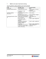
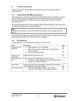
M a l f u n c t i o n s / t r o u b l e s h o o t i n g  

If an error message is output, it appears on the control unit display. 
Please observe the corresponding instructions for the control unit.


Fault 

Possible cause 

Troubleshooting 

Pump noise 

Air in the system 

Bleed 

Insufficient tapping quantity 

Insufficient water pressure 

Check pressure, increase if 
necessary 

Calcification in heat 
exchanger 

Decalcify/replace 

Insufficient tapping 
temperature 

Incorrect adjustment on the 
control unit 

Check settings 

Excessive pressure loss in 
the piping on the heating side 

Check the piping, change if 
necessary 

Drinking water does not heat 
up 

Control unit not in operation. 

Check control unit 

Air in the system. 

Bleed 

HW flow sensor not 
connected correctly, or 
defective. 

Check, replace if applicable 

Heating flow temperature 
sensor not connected 
correctly or faulty. 

Check, replace if applicable 

Pump faulty 

Check, replace if applicable 


Volume flow sensor faulty or 
incorrect type (VFS instead of 
VFD or vice versa) 

Check and replace if 
applicable 


Summary of Contents for FRIWA 30

Page 1: ...P ROD U KTINFORMAT ION Wir entwickeln f r Ihre Zukunft Frischwasserstation FRIWA 30 Solarbayer GmbH 46 15 Technische Beschreibung...

Page 2: ...Deutsch...

Page 3: ...rlust Pumpenkennlinie 7 3 4 Korrosionsschutz 7 3 5 Anschl sse 9 4 Montage 10 4 1 Wandmontage 10 4 2 Hydraulischer Anschluss 11 4 3 Hydraulischer Anschluss mit Zubeh r 12 4 4 Elektrischer Anschluss 13...

Page 4: ...ererw rmung mittels Pufferspeicher und stationsinternem Plattenw rmetauscher im Durchflussprinzip Es darf nur Trinkwasser im Sinne der Trinkwasserverordnung erw rmt werden 1 2 Sicherheitshinweise Nebe...

Page 5: ...svorlauf HVL 12 D mmplatte f r Plattenw rmetauscher 3 Schwerkraftbremse im Kugelhahn 13 Sp lhahn Kaltwasser KW 4 Regelung 14 Handentl ftungsventil 5 Umw lzpumpe 15 W rmed mmschale 6 Kugelhahn Heizungs...

Page 6: ...Heizungsseite Brauchwasserseite 3 bar 10 bar Max Betriebstemperatur Heizungsseite Brauchwasserseite 95 C 65 C Anschl sse Heizungsseite Brauchwasserseite Rp Rp Druckverlust Brauchwasserseite bei Nennle...

Page 7: ...l pH Wert 7 5 9 0 7 0 9 0 Elektrische Leitf higkeit bei 25 C 10 500 S cm Hydrogencarbonat HCO3 70 300 mg l 60 300 mg l Verh ltnis HCO3 SO4 2 Verh ltnis 1 0 Verh ltnis 1 5 Ammoniak NH4 2 mg l Freies Ch...

Page 8: ...lattenw rmetauscherhersteller der Einsatz von Enth rtungsanlagen ab einer Wasserh rte 8 5 dH empfohlen Wasserbehandlungsma nahmen zur Vermeidung von Steinbildung Enth rtung Frischwasserstation mit Vor...

Page 9: ...Art Nr 908 30 62 00 Stand 11 2015 9 3 5 Anschl sse WW Warmwasser KW Kaltwasser HVL Heizungsvorlauf HRL Heizungsr cklauf...

Page 10: ...benstehender Abbildung anzeichnen bohren und Spreizd bel setzen Die obere Schraube mit Unterlegscheibe eindrehen bis Schraubenkopf ca 1 cm Abstand zur Wand hat Station einh ngen mit Wasserwaage ausric...

Page 11: ...15 11 4 2 Hydraulischer Anschluss Beispieldarstellung erhebt keinen Anspruch auf Vollst ndigkeit und ersetzt keine fachm nnische Planung Bezeichnung Beschreibung WW Warmwasser KW Kaltwasser HVL Heizun...

Page 12: ...kulationseinheit thermische Vormischung Weiteres erh ltliches Zubeh r Kaltwasseranschluss Set Verrohrungssatz Speicher Darstellung erhebt keinen Anspruch auf Vollst ndigkeit und ersetzt keine fachm nn...

Page 13: ...teur und entsprechend den rtlich geltenden Vorschriften ausf hren lassen Vor dem Arbeiten die Versorgungsspannung trennen Die Frischwasserstation ist werksseitig komplett vormontiert und vorverdrahtet...

Page 14: ...tationen entstehen wodurch der Str mungssensor besch digt wird Das Heizungssystem inkl Prim rseite der Frischwasseranlage nur mit filtriertem eventuell aufbereitetem Wasser nach VDI 2035 bef llen und...

Page 15: ...inderung der Schwerkraftzirkulation darf der Ventilteller nicht angel ftet sein Der Kugelhahngriff steht senkrecht Die Schwerkraftbremse ist geschlossen Servicestellung SKB ge ffnet Servicestellung En...

Page 16: ...alkung Austausch Zu geringe Zapftemperatur Falsche Einstellung an der Regelung Einstellungen berpr fen Zu gro er Druckverlust der Heizungsseitigen Verrohrung Verrohrung berpr fen ggfs ndern Keine Erw...

Page 17: ...utzung sowie nach Best ndigkeit der W rmetauscherplatten Vom Reinigungsmittelhersteller sollte auf jeden Fall die Best tigung vorliegen dass das Reinigungsmittel den zu reinigenden Plattenw rmetausche...

Page 18: ...Nr 908 30 62 00 Stand 11 2015 18 1 0 P u m p e n i n f o r ma t i o n PWM Logik PWM2 7 Pumpe aus 7 12 Min Leistung Betrieb 12 15 Min Leistung start up 15 95 proportionaler Leistungsbereich 95 Max Leis...

Page 19: ...English...
Page 20: ...istic curve 24 3 4 Corrosion protection 24 3 5 Calcification protection 25 3 6 Connections 26 4 Assembly 27 4 1 Wall mounted assembly 27 4 2 Hydraulic connection 28 4 3 Hydraulic connection with acces...

Page 21: ...storage tank and internal plate heat exchanger via a flow through principle Only drinking water in accordance with the Drinking Water Ordinance must be heated 1 2 Safety instructions In addition to c...

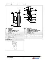
Page 22: ...ting flow HF 12 Plate heat exchanger insulation plate 3 Gravity brake in ball valve 13 Flush valve for cold water CW 4 Control unit 14 Manual vent valve 5 Circulation pump 15 Heat insulating shell 6 B...

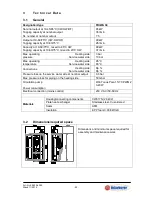
Page 23: ...rvice water side 3 bar 10 bar Max operating temperature Heating side Service water side 95 C 65 C Connections Heating side Service water side Rp Rp Pressure loss on the service water side at nominal o...

Page 24: ...00 mg l Nitrate NO3 50 mg l pH value 7 5 9 0 7 0 9 0 Electrical conductivity at 25 C 10 500 S cm Hydrogen carbonate HCO3 70 300 mg l 60 300 mg l Ratio HCO3 SO4 2 Ratio 1 0 Ratio 1 5 Ammonia NH4 2 mg l...

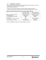
Page 25: ...ommends using water softeners if the water hardness level is 8 5 dH Water treatment measures to prevent scale formation water softening Fresh water station with premix function Fresh water station wit...

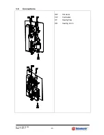
Page 26: ...Art Nr 908 30 62 00 Stand 11 2015 26 3 6 Connections HW Hot water CW Cold water HF Heating flow HR Heating return...

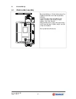
Page 27: ...m holes as per the adjacent illustration and insert expansion anchors Locate the top screw and washer and tighten until the screw head protrudes approx 1cm from the wall Suspend the station align with...

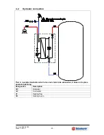
Page 28: ...1 2015 28 4 2 Hydraulic connection This is a sample illustration which does not claim to be exhaustive it does not replace specialist planning Designation Description HW Hot water CW Cold water HF Hea...

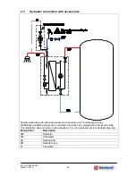
Page 29: ...irculation unit thermal pre mixing Additionally available accessories cold water connection set piping set for the storage tank This illustration does not claim to be exhaustive it is not a replacemen...

Page 30: ...lly applicable regulations Disconnect the supply voltage prior to any work The fresh water station is pre installed and wired ex works Connect the power cable to commission Please refer to the separat...

Page 31: ...the flow sensor Only fill the heating system including the primary side of the fresh water system with filtered treated water as per VDI 2035 bleed the system completely 5 2 First start up Please obs...

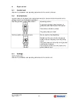
Page 32: ...sition To prevent circulation under the force of gravity the valve head must not be opened The ball valve handle is vertical The gravity brake is closed Service position gravity brake open Service pos...

Page 33: ...alcify replace Insufficient tapping temperature Incorrect adjustment on the control unit Check settings Excessive pressure loss in the piping on the heating side Check the piping change if necessary D...

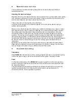
Page 34: ...match the type of contamination and resistance of the heat exchanger plates It is important to obtain confirmation from the cleaning agent manufacturer that the cleaning agent will not cause corrosio...

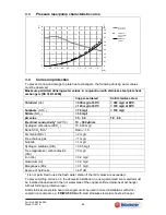
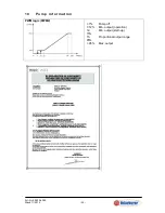
Page 35: ...Art Nr 908 30 62 00 Stand 11 2015 35 1 0 P u m p i n f o r m a ti o n PWM logic PWM2 7 Pump off 7 12 Min output operation 12 15 Min output start up 15 95 Proportional output range 95 Max output...

Page 36: ...st die jeweils aktuelle Fassung dieser Montageanleitung auf unserer Homepage www solarbayer de Systemtechnik aus Bayern Wir entwickeln f r Ihre Zukunft Solarbayer GmbH Preith Am D rrenhof 22 85131 Pol...

Reviews: