Solar Stik
®
Technical Bulletin 2
Effective Date 20150831
800.793.4364
www.solarstik.com
© 2019 Solar Stik Inc.
All Rights Reserved. Solar Stik is a registered trademark of Solar Stik Inc.
SS20190717
10. Turn off Li Expander Pak and reinsert cotter pins.
Page 5 of 8
6. Remove the cotter pin from the Power Switch of all Expander Paks and PRO-Verter 7000-120
and toggle the switches to “ON”.
7. Determine the Battery Status by pushing the button for the Battery Status LED report. Each one
should be GREEN or AMBER.
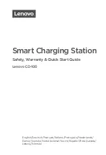
8. Adjust the input amperage
on the PRO-Verter 7000. See
diagram to the right. The diagram
provides setting values for charging using
shore power) and fuel-powered generators.
9. The PRO-Verter LCD user interface will display zero (0) charging amps when the batteries are charged fully and the
LED Status indicator will be GREEN.
NOTICE
*Extending the charge times beyond the minimum will not result in damage to the Li
Expander Pak 2400s. However, they should not be left to charge indefinitely.
Minimum charge times based on AC input amperage
5 amps AC (600 watts of charging power)
~40 hours charge time if the batteries were fully discharged*
10 amps AC (1200 watts of charging power)
~20 hours charge time if the batteries were fully discharged*
15 amps AC (1800 watts of charging power)
~13 hours charge time if the batteries were fully discharged*
30 amps AC (3600 watts of charging power)
~6.7 hours charge time if the batteries were fully discharged*
NOTICE
Failure to properly set
“AC Input”
may overload the AC power source.
F3 AC Input
Amps = 15A
FAVS 3
Press
Top line shows current
FAVS menu and position in FAVS menu
Bottom line shows AC current setting
Push Select to edit current setting
Press to save
Rotate to
desired
amperage:
F3 AC Input
Amps = 30A
F3 AC Input
Amps = 15A
Shore Power
F3 AC Input
Amps = 5A
1 kW GenSet
2 kW GenSet