background image


smoking,  eating  or  drinking  in  the  work  area  and  always  wash  your  hands  before 

eating or drinking. The minimum clearance from the edge of the fire to a combustible 

surface  at  the  side of the fire should be 150mm and if a shelf is installed above the 

fireplace it should be no closer 150mm to the top of the fire.  


If the left and right hand side cheeks need to be removed during installation ensure 

that they are replaced correctly. NB Note that the side cheeks are cut to make a left or 

right-hand cheek. This can be determined by the direction of cut on the angles of the 

cheek and the left-hand cheek has a cut-out for the pilot. If the ceramic backboard 

needs replacing, remove the plastic bag before installation. 


4.2  Place the 3 base boards on top of the burner unit, behind the burner box. (SEE Fig 

6 ). 
 

4.3 Insert burner inserts into burner box channel as shown in 

Fig.6 and 7


4.4  Place the left and right hand side cheeks to sides of fire.  

NB  Direction of cut angles at rear of cheek. 
 

4.5 Insert the front coal blocks into the coal block support shelf

.(SEE FIG 7) 

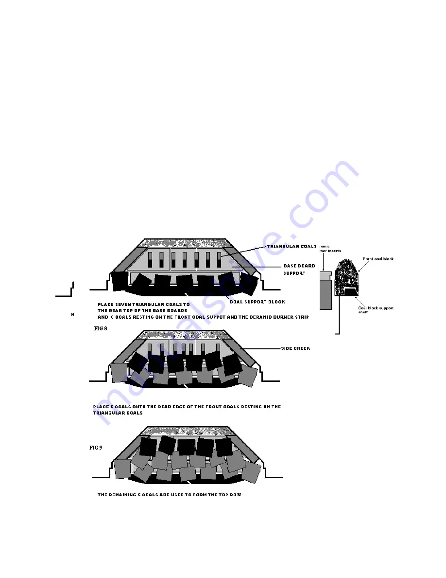
4.6    Position  7  triangular  coals  to  the  rear  top  of  the  base  boards.  Ensure  they  are 

equally spaced 

(See Figs 8 and 9)


4.7  Place 6 large coals along the front coal block support and resting on the ceramic 

burner inserts. 

(See Figs 8 and 9)


Summary of Contents for LANDSCAPE 22

Page 1: ...TIONS IN FORCE THIS PRODUCT IS APPROVED TO THE EUROPEAN GAS APPLIANCE DIRECTIVE This appliance is identified by the Serial Number The Serial Number is found at the top of the data plate to the right of the control knob This serial number must be quoted in all correspondence NB PRIOR TO INSTALLATION ENSURE THAT THE LOCAL DISTRIBUTION CONDITIONS IDENTIFICATION OF THE TYPE OF GAS AND PRESSURE AND THE...

Page 2: ... 3 mm 1 5 mm Weight 20 9 Kg gross NB THIS APPLIANCE IS FITTED WITH A SPILLAGE MONITORING DEVICE WHICH WILL OPERATE IF THE FLUE IS NOT CLEARING THE COMBUSTION PRODUCTS THE FIRE WILL GO OUT IF THIS OCCURS IF THE FIRE GOES OUT SEE SECTION 5 COMMISSIONING THE APPLIANCE IN THESE INSTRUCTIONS WAIT THREE MINUTES BEFORE RE LIGHTING IF THE FIRE REPEATEDLY GOES OUT CHECK THE PILOT BURNER AND THERMOCOUPLE FO...

Page 3: ... is a minimum cross sectional area as described above The flue should be swept before the appliance is fitted except where the installation is to new premises and there is no obvious obstruction from birds nests etc Any flue terminal should have outlets at least equivalent to twice its nominal flue area and conform to those recommended in BS 715 and BS 1289 Siting of terminals is given in BS 5440 ...

Page 4: ... a debris collection space minimum depth of 50mm behind the appliance See Fig 2 Fig 1 Fig 2 2 6 Use of RCF articles in this appliance This product uses fuel effect pieces containing Refractory Ceramic Fibre RCF which are man made vitreous silicate fibres Excessive exposure to these materials may cause temporary irritation to eyes skin and respiratory tract consequently it makes sense to take care ...

Page 5: ...through the lugs on the top of fire box and pull through to the fixed nipple Put the tie wires through the eye fixings and through the two holes in the bottom rear of the fire case Apply the foam seal to the inside of the flange to ensure a perfect seal is maintained around the fireplace opening Position the fire case into the opening put the two tensioning bolts onto the wires together with the l...

Page 6: ... not to damage the long thin fibre burner situated near the front and just behind the front coal block To ensure release of fibres from these RCF articles is kept to a minimum during installation and servicing we recommend that you use HEPA filtered vacuum to remove any dust accumulated in and around the fire before and after working on the fire When replacing these articles we recommend that the ...

Page 7: ... sides of fire NB Direction of cut angles at rear of cheek 4 5 Insert the front coal blocks into the coal block support shelf SEE FIG 7 4 6 Position 7 triangular coals to the rear top of the base boards Ensure they are equally spaced See Figs 8 and 9 ...

Page 8: ...angular coals see Figs 8 and 9 4 9 Remove any protective film from the trim The brass trim is fitted to the casing using the magnets provided Place two magnets on either side of the fire opening equally spaced and position the trim to cover the flange Offer the trim to the flange until the magnets hold the trim to the case NB PRODUCT CARE LABEL ON TRIM SHOULD BE BROUGHT TO THE ATTENTION OF THE CUS...

Page 9: ...ned on 5 2 Turn on the gas at the isolating gas cock 5 3 Press in and turn the main burner control knob anticlockwise whilst keeping it fully depressed until the indicator is opposite PILOT IGN See Fig 11 Repeat this sequence as necessary until the pilot is seen to light This is situated on the left hand side of the burner tray ...

Page 10: ...ontrol clockwise to the OFF position See Fig 11 6 1 CHECKING THE INLET PRESSURE With the fire off remove the pressure test point screw and connect a water manometer to the pressure test point Re light the fire as above and check the manometer this should read as stated in the appliance data details if the pressure is less than this investigate and remedy the cause Turn off the fire and remove the ...

Page 11: ...e user must remove and read 9 5 Leave this instruction manual with the user to be retained in a safe place for future reference 10 SERVICING AND MAINTENANCE 10 1 BEFORE SERVICING IS CARRIED OUT ISOLATE THE APPLIANCE FROM THE GAS SUPPLY ALWAYS CHECK FOR GAS SOUNDNESS AND SPILLAGE AFTER RE FITTING THE APPLIANCE 10 2 With the fire turned OFF and allowed to cool remove the front and fret Carefully rem...

Page 12: ...flue to be swept annually to ensure it is in good condition and free from obstruction 13 RECOMMISSION THE FIRE Refer to clauses 3 8 to 8 5 inclusively Also clauses 6 7 and 8 13 REPLACEMENT PARTS 13 1 GAS TAP AND FSD Disconnect the gas pipes unions pilot tube and thermocouple connections from the gas tap end Pull off gas valve control knob and undo retaining nut at the front of the valve Disconnect...

Page 13: ...x GENMAT GENMAT Fibre backboard GENBAC GENBAC Burner inserts 3 GENINS GENINS Side cheeks 2 CHEEKS CHEEKS Front Coal Block 2 GGFB GGFB Coal Pack A 17 large COALLA COALLA Coal Pack B 7 triangular COALTR COALTR Set of manuals 2 MANULT MANULT Brass Trim GEMTRI GEMTRI Sealing tape SEAL SEAL WARNING When the appliance is used in the presence of young children the elderly or infirm a fireguard is recomme...

Page 14: ...y foreign matter e g cigarette ends onto the fire e Never leave the house unattended with the fire lit for long periods f As with any fire certain parts will become hot during use Care should be taken particularly with the fret and control knob g We recommend the use of a fireguard conforming to BS 6539 be used when in the presence of young children the elderly or infirm h Your appliance is fitted...

Page 15: ...tween high large flame symbol and low small flame symbol 1 8 Note The gas control knob can be depressed and turned fully anti clockwise to the LOW position small flame symbol 1 10 TURNING OFF THE APPLIANCE FOR SHORT PERIODS To turn off temporarily push in and turn the Main Burner control knob clockwise to the IGN PILOT position In this position the pilot flame will stay lit with the fire ready for...

Page 16: ...ll remain alight Standby should be used if the fire is going to be used in a relatively short time i e during the evening To bring the fire out of standby mode press either button on the right hand side of the handset To Turn off the Fire To turn the fire off completely press the top button on the left hand side of the transmitter the fire will extinguish completely It is recommended that the fire...

Page 17: ... face so that you avoid inhaling the dust We do not recommend the use of a normal domestic vacuum cleaner which may blow dust back into the air 3 6 It is recommended that the appliance be serviced annually by a competent person when any debris from the chimney and any soot formed should be removed in accordance with good RCF handling procedures 3 7 RELAYING YOUR GAS COAL EFFECT FIRE Only use the 1...

Page 18: ... cut on the angles of the cheek and the left hand cheek has a cut out for the pilot If the ceramic backboard needs replacing remove the plastic bag before installation 4 2 Place the 3 base boards on top of the burner unit behind the burner box SEE Fig 6 4 3 Insert burner inserts into burner box channel as shown in Fig 6 and 7 4 4 Place the left and right hand side cheeks to sides of fire NB Direct...

Page 19: ...aller carries out the installation b That the fireplace conforms to British Standards for Class One Appliances c That our cleaning and handling instructions for are adhered to The guarantee does not cover mishandling normal wear and tear or possible discolouration of parts d That the guarantee card supplied with the appliance is returned to us for registration within four weeks of the date of purc...

Reviews: