


Manual 2100-707D
Page
7 of 39
Ducted Applications
Field fabricated supply and return duct work may be
installed inside the structure being conditioned. A short
supply and/or return stub duct may be connected to the
unit supply and return flanges before unit installation to
help with duct connections inside the structure. Supply
and return ducts must be properly sized for the design
airflow requirement of the equipment. Air Conditioning
Contractors of America (ACCA) is an excellent guide
to proper sizing. All duct work or portions thereof not
in the conditioned space should be properly insulated
in order to conserve energy, reduce heat conductivity,
and prevent condensation or moisture damage. Refer
to the Maximum External Static Pressure (ESP) of
Operation Table on page 34. Design the duct work
according to methods given by the Air Conditioning
Contractors of America (ACCA). When duct work is
installed in unheated spaces, it should be insulated
with a minimum of 1" of insulation. Use insulation with
a vapor barrier on the outside of the insulation. Flexible
joints should be used to connect the duct work to the
equipment in order to keep the noise transmission to a
minimum. Ducts through the walls must be insulated
and all joints taped or sealed to prevent air or moisture
from entering the wall cavity.
Model series J18 and J24 are approved for 0" clearance
to the supply duct. For model series J30 and J36, a
1/4" clearance to combustible material for the first 3'
of duct attached to the outlet air frame is required. See
instructions on page 8 and Figures 3 − 7 (pages 11 –
15) for further details.
this manual. A non-restrictive metallic supply air grille
with deflectors is required for free blow applications.
Contact the local distributor or visit www.bardhvac.com
for ordering information.
A metallic return air grille is required for non-ducted
applications. The spacing between louvers on the grille
shall not be larger than 5/8". It is recommended that a
Bard Return Air Grille Kit is installed that is designed
specifically for the wall mount product. Contact the
local Bard distributor or visit www.bardhvac.com for
ordering information. A field-supplied return grille
that meets the 5/8" louver criteria and does not cause
the unit to exceed the maximum specified external
static pressure (ESP) may be used. If using a return
air filter grille, filters must be of sufficient size to
allow a maximum velocity of 400 fpm. Filter return
air grilles do not filter air being brought into the
structure through ventilation options including fresh air
dampers, ventilators, economizers and energy recovery
ventilators. Be sure to install the return grille with the
louvers pointed downward towards the floor. This will
help ensure return air is drawn upward from the floor
and improve air circulation in the room.
NOTE:
If no return air duct is used, applicable
installation codes may limit this cabinet to
installation only in a single story structure.
Thermostat or Indoor Temperature Sensor Placement
The location and installation of the thermostat or
temperature sensor that monitors indoor temperature is
very important regarding unit operation. Avoid placing
the thermostat in an area exposed to direct sunlight
or air from doorways leading outdoors. Use a piece
of insulating material to close off conduit openings
or holes in the wall surface for wire entry into the
thermostat or temperature sensor. This will help avoid
non-conditioned air from entering the thermostat
and effecting temperature and/or humidity readings.
As common practice, the thermostat or temperature
sensor should measure the temperature of the air
being returned to the unit, and not the conditioned
air being supplied by the unit. Placing the thermostat
or temperature sensor near a return air opening will
normally result in optimal unit performance.
Unit Installation
Make sure to have the proper tools at the work site that
are needed for unit installation. The following steps
are provided to ensure the unit is installed properly to
the wall surface, and that the unit will provide years of
service with minimal service requirements.
Materials/Tools List
Additional hardware and miscellaneous supplies are
needed for installation. These items are field supplied
and must be sourced before installation. The following
list also includes tools needed for installation.
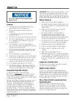
Fire hazard.
Maintain minimum 1/4" clearance between the
supply air duct and combustible materials in
the first 3' of ducting.
Failure to do so could result in fire causing
damage, injury or death.
!
WARNING
Free Blow Applications
Some installations may not require extensive supply
duct work throughout the structure and are referred
to as free blow applications. A short field-fabricated
supply duct must be used in the wall cavity to
transition between the supply collar on the unit and
the supply louver grille in the room. The duct must
be properly insulated in order to conserve energy,
reduce heat conductivity and prevent condensation
or moisture damage. All joints must be taped or
sealed to prevent air or moisture entering the wall
cavity. Follow all clearances including distances to
combustible materials and all instructions provided in