S4KC SEriES USEr mAnUAL |
23
7.
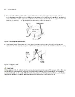
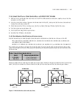
insert the equipment, with inner members attached, into the bracket assemblies by inserting the top and bottom
edges of the inner members into the top and bottom curved tracks of the front members. Slide the equipment into
the rack (see Figure 17). The ends of the inner members are tapered to allow the rear of the equipment to be angled
upward before insertion, if space allows. The equipment should move smoothly into the bracket assemblies. if it does
not, recheck the alignment of the front and rear members from Steps 2 and 3.
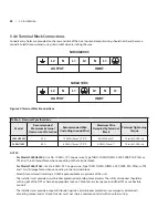
Insert the UPS into the front members.
Lift the front and push it into the rack.
Figure 17: Insert the UPS
8.
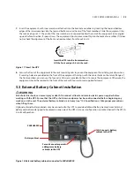
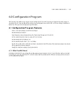
Secure the front of the equipment to the rack mounting rails to prevent the equipment from sliding out of position.
if securing holes are provided on the front of the equipment that align with the center holes on the return flange of
the front members, you can use the four extra m5 screws provided in the kit to secure the equipment. Otherwise, the
equipment should be secured to the front of the rack with four customer-supplied fasteners.
5.3 External Battery Cabinet Installation
!
wARNINg
Risk of electric shock; can cause injury or death. Disconnect all local and remote electric power supplies before
working with the UPS. Ensure that the UPS is shut down and power has been disconnected before beginning any
work on or in the unit. The external battery cabinet(s) are heavy (see “12.0 Specifications). Take proper precautions
when lifting them.
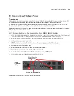
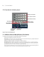
Optional external battery cabinets may be connected to the UPS to provide additional battery backup times. External
battery cabinets are designed to be placed on one side of the UPS in a tower configuration or stacked beneath the UPS in
a rack configuration.
Cable connects battery
cabinet to the UPS
S4K4U6000C
Battery cabinet
Second connector permits
adding more battery
cabinets to the UPS
Figure 18: External battery cabinets connected to S4K4U6000C


