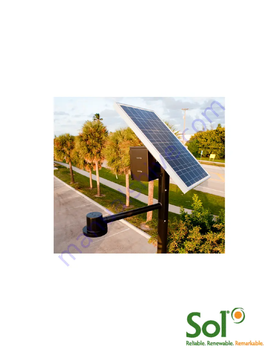
GreenWay™
Solar LED Path and Trail Lighting System
Installation and Owner’s Manual
Page 1: ...GreenWay Solar LED Path and Trail Lighting System Installation and Owner s Manual ...
Page 2: ... void all warranties Installation and or troubleshooting should be performed only by qualified personnel Follow local codes at all times during installation of the GreenWay Be very careful when working with batteries Do not allow bare ends of the wires to touch each other or grounded metal parts while connected to the controller This will damage the controller CONTENTS Section 1 Site Selection and...
Page 3: ...he solar panels are shaded during part of the day will prevent the solar panel from fully charging the battery reducing the hours of nighttime illumination and possibly damaging the battery If installed near a tree check the tree branches every three months and trim when needed Installation of the solar light system and pole must comply structural engineering requirements for local and national co...
Page 4: ... 101 302012 103 1 1 1 Arm Assembly 302012 201 1 1 1 Battery 86008 001 1 1 1 Battery Box 202721 200 1 1 1 Solar Panel Harness 855200 031 1 1 1 Battery Harness 855200 002 1 1 1 LED Harness 805000 004 1 1 1 aiSUN Controller 855101 200 1 1 1 aiSUN 56L Single Battery Harness 855200 010 Solar Panel Assembly Mounting Hardware GWHP PV 4 4 4 Battery Box Mounting Hardware GWHP BB 4 4 4 Drive Rivets DR375X 5...
Page 5: ...the arm assembly until the connector plug emerges from pipe end of the arm assembly opposite side of luminaire install holes Figure 4 FIGURE 5 ATTACHING PV ASSEMBLY TO PV MODULE Attaching the PV Module to the PV Mount Lay the PV module upside down on a protected surface cardboard shipping carton can be used and position the PV mount over the PV module so that the hole and grommet on the side of th...
Page 6: ... fixture which will be attached to the end of the arm is in the desired orientation Using one of the pilot holes at the upper end of the pole as a guide drill one rivet hole using a U S W gauge 0 386 inch drill bit or use a 25 64 inch drill bit if W gauge not available Drill through the pilot hole and then through the arm assembly stock beneath the pilot hole drill rivet one pilot hole at a time P...
Page 7: ...ee unconnected ends of the battery harness from touching other metal parts so they will not accidentally cause a short Tighten the connection on both terminals Place the battery in the battery box Connect the battery harness to the single aiSUN harness as shown in Figure 11 Battery Harness one for each battery Black Red Gel Cell 100 Ah NRGLife Battery FIGURE 11 BATTERY AND BATTERY HARNESS Installi...
Page 8: ...DIAGRAM Battery 1 Black Red Battery Harness aiSUN Controller PV Module LED Luminaire Brown Blue Luminaire Load Cable Black Red Green Ground aiSUN Single Harness Black Orange This lamp LED is in excess of the Exempt Risk Group defined in IEC 62471 2006 07 This lamp LED has been found to be in the Risk Group 2 classification at an exposure distance of 20 cm or less from the glass surface of the lamp...
Page 9: ...iSUN turns on the LED luminaire after sunset and turns off the luminaire before sunrise as configured per each location This includes dimming and response to motion detection in some configurations aiSUN is factory configured for your location No adjustments are required Lights are programmed to run in one several operating modes Operating mode is shown on the unit label as HH LLL LLL HH LLL 1 2 3...
Page 10: ...s Several diagnostic LEDs will turn on remain on for several seconds This is normal FIGURE 15 aiSUN SYSTEM TEST Troubleshooting and Diagnostic LEDs If the LED Luminaire turns on to full brightness system operates OK and will automatically turn on off with sunset and sunrise If the LED Luminaire does not turn on as described follow the Diagnostic LED table below to troubleshoot the system If LED Lu...
Page 11: ...lly requires a larger solar panel and more battery reserve to provide more light longer These types of changes are costly but are possible contact SOL Inc Q What does aiSUN stand for A ai stands for adaptive intelligence SUN indicates that aiSUN is for solar charging Frequently asked Questions about aiSUN Diagnostic LEDs aiSUN has diagnostic LEDs to indicate of the status of the Solar Light it is ...
Page 12: ...ht is designed to provide reliable operation and illumination all year The solar panel provides enough energy during a normal day to charge the battery for operation of the LED fixture for the following night The system is designed with a five day reserve charge As a result extended periods of low sun may deplete the five day reserve and affect performance of the system The following conditions ma...
Page 13: ...ert the new fuse and replace the fuse cover 4 Test the system 5 Close the battery box LED Fixture Replacement 1 Remove the socket head bolts that secure the LED fixture to the arm see Figure 14 for details 2 Slide the LED fixture off the arm 3 Disconnect the LED fixture from the load cable 4 Insert the new LED fixture following Steps 1 through 4 on page 5 Open the battery box and press the white T...
Page 14: ...sconnect the battery harness from the old battery and attach to the new battery 5 Place the new battery in the battery box 6 At the controller connect the aiSUN single harness to the battery harness then connect the solar array harness 7 Replace the battery box cover Caution When disconnecting the cables be sure to disconnect the solar array harness first Caution When reconnecting the cables be su...
Page 15: ...two to three days of consecutive sunny weather to charge the battery pack Low battery voltage caused by shading of the solar panel Clear tree branches and other obstructions from the vicinity of the solar panel The battery is bad Replace the battery The red LED on the controller remains illuminated Low battery voltage caused by inclement weather Allow for two to three days of consecutive sunny wea...
Page 16: ...e of the unit shall not exceed the purchase price of the system The purchaser assumes and will hold harmless SOL Inc in respect of all such loss For warranty service on SOL products please contact SOL Inc for a Return Material Authorization RMA number by calling 1 772 286 9461 Any products or components that are returned to SOL without first obtaining a RMA may not be issued any credit and SOL sha...
Page 17: ...g returned Serial Number of the product being returned A description of the problem The address to which the repaired or replaced product is to be shipped Equipment being returned must be properly packaged to protect it from damage during shipment Shipping costs and insurance to SOL Inc are the responsibility of customer Upon verification of failure due to defects in materials or workmanship we wi...