background image

®

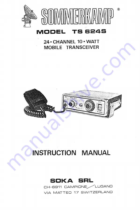
MODEL  T S   624S

24- CHANNEL  10 - WATT 

MOBILE  TRANSCEIVER

INSTRUCTION  MANUAL

ВОКА  SRL

CH-6911  C A M P IO N E /^ LUGANO 

VIA  MATTEO  17  SWITZERLAND

Summary of Contents for SOMMERKAMP TS 624S

Page 1: ... MODEL TS 624S 24 CHANNEL 10 WATT MOBILE TRANSCEIVER INSTRUCTION MANUAL ВОКА SRL CH 6911 CAM PIONE LUGANO VIA MATTEO 17 SWITZERLAND ...

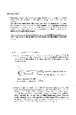
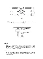
Page 2: ...ound system a Since the cabinet is commonly connected to all В minus potentials in the transceiver the transceiver must be electrically isolated from the chassis of the vehicle at all times See Fig 1 for connection with power source О J fusF TO CAR CHASSIS TO IGNITION OR BATTERY TRCV CHASSIS TO BE INSULATED FROM CAR b Obtain a pair of 0 01 mfd 500V ceramic capacitors Cut the antenna coaxial cable ...

Page 3: ...NA Antenna is one of the most important factors to the operation with maximum efficiency A quarter wave antenna can be successfully mounted for möbile station The antenna impédance should be 50 ohms For the details consult with your distributor Important Do not operate the transceiver without a proper antenna or dummy load connected to the antenna connector as the transmitter transistors may be da...

Page 4: ...ity may be reduced 3 Turn the channel selector knob for the desired channel 4 For transmitting press the button on the microphone and speak into it normally Release the button for receiving METER The meter reading indicates the signal strength at receiving and fonctions as an output indicator at transmitting and the meter pointer should be within the blue zone under the normal conditions TONE LIGH...

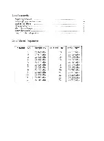
Page 5: ... frequencies CHANNEL NO FREQUENCY CHANNEL NO FREQUENCY 1 26 965 Mhz 13 27 115 Mhz 2 26 975 Mhz 14 27 125 Mhz 3 26 985 Mhz 15 27 135 Mhz 4 27 005 Mhz 16 27 155 Mhz 5 27 015 Mhz 17 27 165 Mhz 6 27 025 Mhz 18 27 175 Mhz 7 27 035 Mhz 19 27 185 Mhz 8 27 055 Mhz 20 27 205 Mhz 9 27 065 Mhz 21 27 215 Mhz 10 27 075 Mhz 22 27 225 Mhz 11 27 085 Mhz 23 27 255 Mhz 1 2 27 105 Mhz 24 27 275 Mhz 4 4 t ...

Page 6: ......

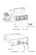
Page 7: ...RF POWER S METER CHANNEL SELECTOR CALL LAMP ANT CONNECTOR DC POWER EXT SP PŁUG ...

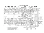
Page 8: ...TS 624S SCHEMATIC DIAGRAM 01 REC RF 02 Ist MIXER Q3 2ndMIXER 0 4 Ist IF Q5 2nd IF 0 6 CALL 0 7 AF PRE 0 8 AF DRIV 09 010 AF POWER Y6 37 850 YÎ5 37 890 ...

Reviews: