INSTALLATION
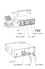
Mounting bracket and screws are supplied for mounting the transceiver
underneath the dashboard. Microphone hanger and screws are also
supplied.
For electrical connection, first make sure that the transceiver is turned
off. Connect the red wire to the ACC terminal of the ignition switch or
+ terminal o f battery and ground the black wire to the chassis of the
vehicle. The black wire should be grounded as short as possible to
minimize the noise interférence.
This transceiver is designed for use with the
n egativ e
ground system.
(For installation in the positive ground system, see the following instruc
tions.)
Installation in positive ground system:
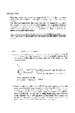
a) Since the cabinet is commonly connected to all В minus potentials
in the transceiver, the transceiver must be electrically isolated from
the chassis of the vehicle at all times. (See Fig. 1 for connection with
power source.)
О)
J
fus
F ) -
-TO CAR CHASSIS ( + )
TO IGNITION OR BATTERY ( - )
TRCV CHASSIS TO BE
INSULATED FROM CAR
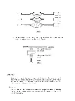
b) Obtain a pair of 0.01 mfd. @500V ceramic capacitors. Cut the
antenna coaxial cable approximately 3 inches from the male connector.
Connect one o f the 0.01 capacitors in linę with the center copper
wire of the coaxial cable and solder. Tape the connections. Add the
other capacitor in line with the shielding braids and solder. Tape the
entire exposed braids and capacitor for insulation. These capacitors,
in line with the conductors of the coaxial cable,now isolate the antenna
ground from the ground o f the transceiver. (See Fig. 2)


