3.2.1
Overview of module configuration parameters
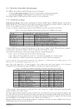
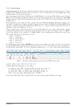
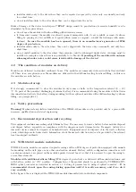
Overview of configuration parameters that can be used for user settings of the WB169-430 module is shown in the
Table
below. The parameters are presented in the same order as they appear in the List of all configuration
parameters (see paragraph
Table 2: Overview of WB169-430 module configuration parameters
Item
Name
Type
Description
Default.
1
Timezone
number
Time zone (time from UTC)
1
2
MBUS ID
0 - 99999999
Serial number (M-Bus address)
read only
3
MBUS Version
0 - 255
Generation or version (M-Bus address suppl.)
read only
4
MBUS Manufacturer
code
Device producer (M-Bus address suppl.)
read only
5
MBUS Medium
code
Medium (M-Bus address suppl.)
07
6
MBUS Power
1 - 5
Transmitting power
3 (20 dbm)
7
MBUS Mode
1 - 2
Communication mode
1 (N1)
8
WMBUS Channel
1 - 7
Frequency channel
1
9
Send periode
0 - 65535
Broadcasting period in minutes
60
10
Sensus meters
ID
list of read iPERL watermeters
11
Encryption
code
Encryption key
disabled
12
Next send
curr. status
Time to next message in minutes
read only
13
No. sent
curr. status
No of sent messages from reset
read only
14
No. recv
curr. status
No of received messages from reset
read only
15
Conf. version
curr. status
No of stored images since last FLASH erasure
read only
16
SW version
curr. status
version number and date of issue
read only
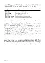
In the
”
Type”
column there is a data type of the parameter.
”
Code” indication in this field means that the value
is displayed in hexadecimal code (couple of hexadecimal characters means 1 Byte) with one exception - IP-address
is indicated in common form (four decimal octets separated by dots). ”Curr. status” indication means that the
field contains current value of operational parameter that cannot be influenced. Range of numbers means that there
could be a number from mentioned range.
In the
”
Default”
column there are default (factory) settings of the parameter. Colour marking of this field has
following meaning:
•
green colour - commonly used parameters that should be set in reliance on the specific usage
•
red colour - parameters that are not recommended to change
•
grey colour - values that cannot be changed (
”
read only”)
Yellow colouring
of the
”
Item” number highlights the parameters, that can be configured by using of
USB-IRDA
optical converter
as described in details in chapter
”
Setting of parameters by using of optical
”
USB-IRDA”
converter”.
WB169-430
17

