background image

Info”

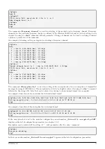
command can be used for setting of device name that is a part of each broadcasted message (see para-

graph

3.3

). The parameter is preset from the factory to

none (no entry)” value. By using of

info”

command

(without parameter) an actual value of the name can be displayed. The device name can be set by entering of any
string of characters after

info” command.

Example of displaying, setting and follow-up checking of the device name:

cfg#info
MBUS manuf info

: ’ABC’

cfg#info XYZ
Change MBUS manuf info from : ’ABC’ to : ’XYZ’
cfg#info
MBUS manuf info

: ’XYZ’

cfg#

Maximum length of the string is 29 characters. The only basic set of characters can be used (without diacritics).
It is not recommended to change this parameter.

Periode”

command serves for setting of broadcasting period of regular info messages. The value of the parameter

is factory preset to 60 minutes. Current value can be checked by

periode”

command (without parameter).

Broadcasting period can be changed by entering of required number of minutes after

periode” command.

Example of displaying, setting and follow-up checking of broadcasting period:

cfg#periode
Periode is 60 min.
cfg#periode 30
Periode changed from 60 to 30 min.
cfg#periode
Periode is 30 min.
cfg#

Group of

power”

(transmitting power),

chan”

(frequency channel),

mode”

(communication mode) and

ekey”

(encryption key) commands is intended for setting of module

RF-subsystem parameters

.

The command

Power”

is used for adjusting of the module broadcasting power. Factory setting is 100 mW

(average power). Actual value of the power can be displayed by using of the

”power”

command without parameter.

Transmitting power can be set-up by entering of the number of power level. There are five levels available:

- value ”1” for transmitting power 14 dBm (25 mW)
- value ”2” for transmitting power 17 dBm (50 mW)
- value ”3” for transmitting power 20 dBm (100 mW)
- value ”4” for transmitting power 24 dBm (250 mW)
- value ”5” for transmitting power 27 dBm (500 mW)

An example of checking, setting and re-checking of transmitting power:

cfg#power
MBUS power : 3 (20 dBm)
cfg#power 5
MBUS power changed from 3 to 5 (27 dbm)
cfg#power
MBUS power : 5 (27 dBm)
cfg#

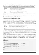
The command

Communication mode”

is used for selecting of the module’s communication mode. Factory

setting is N1 (unidirectional), actual setting can be checked by using of

mode“

command without parameter.

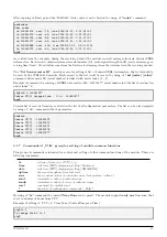
Change of mode can be done by entering of desired option as a parameter of the command. Communication modes
are defined by the Wireless M-BUS standard, accurate choice of relevant communication modes of the module is
stated in the line ”mode” of ”Help” summary (see the paragraph

3.1

).

An example of checking, setting and re-checking of communication mode:

WB169-430

8

Summary of Contents for WB169-430

Page 1: ...WIRELESS COMMUNICATION SYSTEM Wireless M Bus WB169 430 Revision 1 0 SOFTLINK s r o Tomkova 409 278 01 Kralupy nad Vltavou Czech Republic Phone 420 315707111 e mail sales softlink cz www softlink cz...

Page 2: ...information message 18 3 3 2 Alarm message 20 4 Operational conditions 21 4 1 General Operation Risks 21 4 1 1 Risk of mechanical and or electric damage 21 4 1 2 Risk of premature battery discharge 21...

Page 3: ...list of watermeters in reach acquired by RADAR function 16 5 View of WB169 430 module information message received by WMBUSAN4 analyzer 19 6 Encrypted and decrypted message of the WB169 430 module 19...

Page 4: ...e used as a local communication gateway for remote reading of Sensus iPERL series watermeters The module receives regular radio messages with readings Bubble Up messages from watermeters in its radio...

Page 5: ...it must be ordered separately The module is power supplied by internal battery with up to 8 years lifetime for frequency of 6 broadcastings per day Battery lifetime can be negatively influenced by sho...

Page 6: ...32 Transmission speed 9600 Baud Operation mode asynchronous Transmission parameters 8 data bits 1 stop bit none parity Signal level TTL CMOS Optical configuration interface Transmission speed 115 200...

Page 7: ...f wacoSystem product family devices The description and meaning of the parameters that can be changed by optical converter can be found in the section 3 2 Setting of parameters by using of optical IRD...

Page 8: ...period in minutes mode Set WMBUS mode 1 N1 2 N2 chan Set WMBUS channel type for help ekey Set encrypt key W MBUS point no encrypt skey Set encrypt key Sensus sid index value Set Sensus meter ID Modem...

Page 9: ...to the saved set ie there are no differences between commands in FLASH and in the operating set the module will report prompt in the format mon If operating configuration was changed so that it no lon...

Page 10: ...standard each type and modification of the device could have its own line of serial numbers The code is read only type for the WB169 430 module and cannot be changed Assigned version number can be dis...

Page 11: ...g power chan frequency channel mode communication mode and ekey encryption key commands is intended for setting of module RF subsystem parameters The command Power is used for adjusting of the module...

Page 12: ...kbps 3 chan 2a 169 43125 Mhz 2 4 kbps The command Encryption key is used for setting of the encryption key for an encryption of transmitted messages by using of AES 128 key The encryption key of 16 by...

Page 13: ...etting of reading data from Sensus iPERL watermeters There are following commands skey setting of encryption key for decrypting of watermeter messages recvwin open 433 MHz receiving window for preset...

Page 14: ...eter with 130551477 serial number into the list of read meters under index 4 cfg sid 4 130551477 Sensus ID 4 changed from 0 to 130551477 mon Current list of read watermeters is stated in the list of a...

Page 15: ...ns command can be used for displaying of current values of A D converters measuring battery voltage and processor temperature This command is intended only for module checking and diagnostics cfg sens...

Page 16: ...of FLASH memory In the SW version row there is a module software version and release date 3 2 Setting of parameters by using of optical converter The module i equipped with the IRDA infrared optical...

Page 17: ...M Bus identification the default value of the Medium parameter is 07 Water More detailed description of the variable and possibilities of its setting are explained in details in section 3 1 4 Commands...

Page 18: ...iables WMBUS Mode WMBUS Channel and WMBUS Power are used for settings of radio frequency subsystem of the module More detailed description of these variables and possibilities of their setting are exp...

Page 19: ...t of watermeters in reach acquired by RADAR function As evident from the pictures the application enables performing of following settings setting of list of watermeters to be read setting of transmit...

Page 20: ...s from reset read only 14 No recv curr status No of received messages from reset read only 15 Conf version curr status No of stored images since last FLASH erasure read only 16 SW version curr status...

Page 21: ...gnalizes low battery volatge item Signature contains encryption type and parameter 00 00 means no encryption If the message has been re transmitted repeated item Signature is modified by Wireless M Bu...

Page 22: ...ncryption the total number of data block bytes must be rounded into integer multiple of 16 Byte i e 16 32 48 64 etc Bytes Rounding of the message is performed by inserting of required number of 2F blo...

Page 23: ...r more other segments carrying additional information relevant to the alarm typically current status in time of its arising Event of RESET type is always followed by one variable of of Reset Code type...

Page 24: ...ation It is recommended to lead antenna and signal cables as far from 230 50 Hz power cables as possible 4 1 2 Risk of premature battery discharge The devices are equipped with the long duration batte...

Page 25: ...ecommended storing the modules with batteries disconnected and activate the battery during mounting with exception of modules with additional sealing by silicon filling see paragraph 4 2 4 4 Safety pr...

Page 26: ...the module to a suitable firm object wall pipe by two screws or by a clamping tape There are mounts by the box sides for the attachment The recommended position of the mounted module is in the way th...

Page 27: ...le mechanical damage The radio signal conditions can be estimated empirically on the base of previous experience or examined by measuring of the signal strength by the reference transmitter receiver 4...

Page 28: ...after each repair and replacing of the module it is recommended to check functionality of its broadcasting with using of common Master receiver RF analyzer or any other convenient device If the WB169...

Page 29: ...of all broadcasting data i e readings processor temperature and battery voltage If some of the parameters goes beyond the common steady value it is recommended to contact the installation site caretak...

Page 30: ...gnal caused by construction works or any construction changes within the premises or by operation around the installation site moving of machines cars etc permanent periodical or occasional interferen...

Page 31: ...module subsystems in following order check correctness of setting of the module in the central system database check functionality of power supplying as described in the paragraph 5 1 1 Power supplyi...

Page 32: ...ss M BUS WM868 WACO WS868 Sigfox or NB NB IoT series of the modules can be found on the manufacturer website www wacosystem com www softlink cz If interested in any additional information related to a...

Reviews: