Chapter 7 - Display and controls in stand-alone m ode
32
PROFIBUS Tester BC-700-PB - User Manual
7
Display and controls in stand-alone mode
The PROFIBUS Tester 5 always starts in stand-alone mode unless it is USB connected to
a PC or notebook. The readings are shown on the graphical display. You can control the
tool with the four softkeys, the scroll wheel and the push button in center of the scroll
wheel (see
).
When you establish a USB connection during stand-alone mode while a test is running,
the test will be aborted and the tool will be reset (restarted). The display briefly shows:
"Switching to PC mode".
7.1
Main display
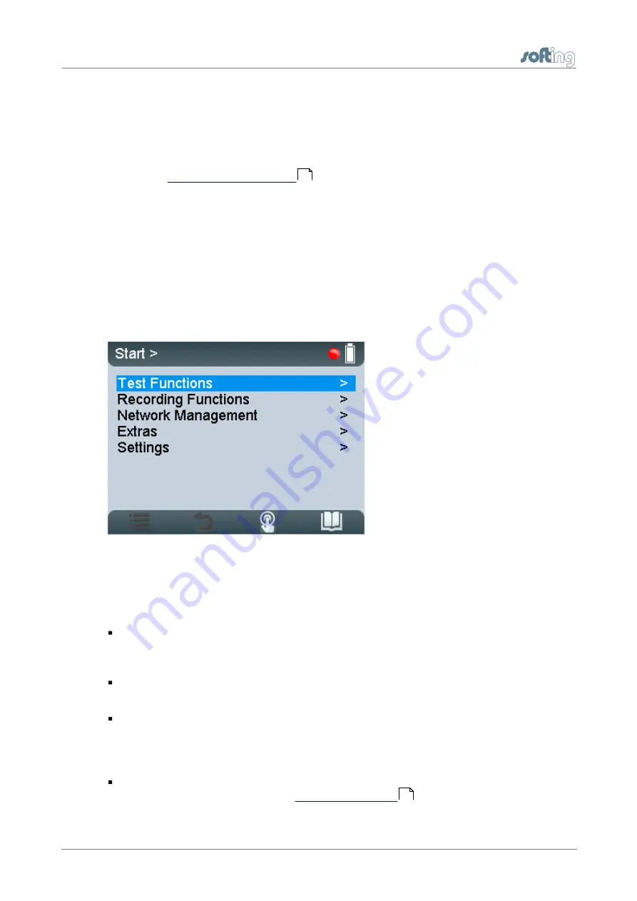
The start page is displayed after start-up in stand-alone mode (or when all dialogs or
functions have been stopped and you have been returned to the main menu). The main
menu is your starting point where you can open any of the test functions or additional
administrative functions.
Figure 26: Start menu
7.2
User interface
The user interface of PROFIBUS Tester 5 comprises four parts:
Device Status in the upper right corner, which provides information such as the
battery charge level indicator, system load status, memory information, state of
master simulator, connected interfaces and adapters,…
Application Status at the upper edge on the left displays which function or sub-function
is currently selected.
The Workspace in the center of the graphical user interface contains the start page,
detail views for the bus analyzes and views for administrative purposes. At a glance
the user views the most important information with respect to the selected test
function.
Control information is shown at the lower edge of the user interface. The meaning of
the four softkeys is explained in
.
14
34


