


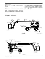


Controls and Indicators
T40RT/T46JRT – 1430001
7
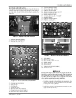
11. Controls selector switch
12. Ground operation switch
13. Platform overload light
14.
Engine/emergency power switch
15. Boom extension switch
16. Boom elevation switch
17. Jib articulation switch – T46JRT
18.
Rotation switch
19. Platform rotation switch
20. Platform level switch
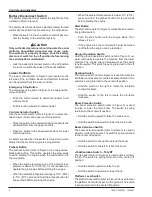
Figure 4 – Upper Controls and Indicators
21. Horn switch
22. Drive range switch
23. Drive/boom selector switch
24. Boom joystick
25. Drive joystick
26. Steer switch
27. Upper control circuit breaker
28. Preheat switch
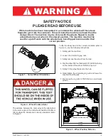
Danger
Pinch points may exist between moving components.
Death or serious injury will result from becoming
trapped between components, buildings, structures,
or other obstacles. Make sure all personnel stand
clear while operating the aerial platform.
Controls to position the platform are located on the
lower control panel on the turntable and on the upper
control panel in the platform.
Controls to drive the aerial platform are located on the
upper control panel only.
•
•
Controls and Indicators
The operator shall know the location of each control and
indicator and have a thorough knowledge of the function
and operation of each before attempting to operate the
machine.
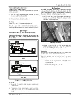
Figure 2 – Battery Disconnect Switch
1. Battery disconnect switch
2. Glow plugs circuit breaker
3. Throttle circuit breaker
Figure 3 – Lower Controls and Indicators
4. Emergency stop button
5. Hour meter
6. Start switch
7. Preheat button
8. Main system circuit breaker
9. Relays/sensors circuit breaker
10. Boom functions circuit breaker
24
1
2
14
18
15
3
4
5
6
7
8
9
10
12
11
13
16
17
19
20
13
20
14
4
21
22
23
19
15
17
6
28
25
26
27
Summary of Contents for 16GTRD
Page 2: ......


