background image

Controls and Indicators

10 

T40RT/T46JRT – 1430001

Preheat Switch

The preheat switch (refer to Figure 4) is a momentarily 

on toggle switch. This switch operates the glow plugs to 

aid in starting the engine when the start switch is in the 

on position.

When the engine is warmed up or the ambient tem-

perature is above 10°C (50°F), it is not necessary to 

operate the glow plugs before starting the engine.

When the ambient temperature range is 10°C (50°F) 

to -5°C (23°F), press and hold the preheat button for 

five seconds before starting the engine.

When the ambient temperature is below -5°C (23°F), 

press and hold the preheat button for ten seconds 

before starting the engine.

Start Switch

The engine can be started from the platform using the 

start switch on the front of the upper control panel (refer 

to Figure 4).

This switch is similar to an automobile ignition switch. 

Turn the switch to start until the engine starts, then 

release it to on.

If the engine dies, the switch must be turned to off 

before it can be turned back to start.

An alarm sounds, when the switch is turned on, to warn 

others that the machine engine is being started.

Note

On some machines it may be necessary to pause about 

three seconds in the on position before going to start so 

the starter can engage.

If the platform is to stay in a particular position for a long 

time, turn the start switch to off to shut off the engine and 

save fuel.

Emergency Stop Button

The emergency stop is a two-position, red push button on 

the top of the upper control panel (refer to Figure 4).


Push the button inward to disconnect power from all 

control circuits at the upper controls.

Pull the button outward to restore power.

Note

The lower controls override the upper controls. If the up-

per control emergency stop button is engaged the lower 

controls can still be used to operate the aerial platform.

Push the emergency stop button inward when the 

upper controls are not in use to protect against unin-

tentional operation.

Drive/Boom Selector Switch

The drive/boom selector switch has two positions to select 

either machine drive or boom function operation  (refer 

to Figure 4).


Place the switch downward in the drive position to 

operate the drive functions.

Place the switch upward in the boom position to oper-

ate the boom functions.

Note

Boom and drive functions can not be operated at the 

same time.

Drive Joystick

The drive joystick (refer to Figure 4) is used to control 

forward and reverse motion of the aerial platform. It is 

also used to steer the machine. The steering and drive 

functions may be operated simultaneously.

Note

The distance the joystick is moved is proportional to the 

speed of the function.

  •  Hold the joystick forward to move the aerial platform 

forward and backward to move in reverse as indi-

cated by the directional arrows on the chassis.

  •  To steer to the right, hold down the right side of the 

steer switch. To steer to the left, hold down the left 

side of the steer switch.

Note

The steering wheels are not self-centering. Set the steer-

ing wheels straight ahead after completing a turn. 

Drive Range Switch

The drive range switch (refer to Figure 4) has two posi-

tions to select drive wheel operation when the booms are 

in the stowed position; tip boom fully retracted and main 

boom fully lowered.

  •  High range (rabbit) – high speed drive with booms in 

the stowed position.

  •  Mid range (turtle) – low speed with high torque drive 

operation with booms in the stowed position.

The drive range operates in low speed when the booms 

are out of the stowed position, regardless of the position 

of the drive range switch. 

Boom Joystick

The boom joystick (refer to Figure 4) is used to raise 

and lower the main boom and to rotate the turntable. 

The  boom  and  turntable  functions  may  be  operated 

simultaneously.  

Note

The distance the joystick is moved is proportional to the 

speed of the function

.

Summary of Contents for 16GTRD

Page 1: ...December 2012 Part Number 1430001 MANUAL OPERATORS Serial number 000000 and after Replaces June 2012...

Page 2: ......
Page 3: ...ation Switch T46JRT 11 Platform Level Switch 11 Platform Rotation Switch 11 Engine Emergency Power Switch 11 Horn Switch 11 Platform Foot Switch 11 AC Generator Switch 11 Hydraulic Oil Warm Up Switch...

Page 4: ...penprufung Zertifikat Nr Examen type CE Numero de Certificat Inspeccion tipo CE Numero de certificado Attestato di certificazione CE nr Onderzoek van het type EC Certificaatnummer EU typkontroll Certi...

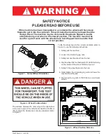
Page 5: ...ut only ever when in the stowed position The machine must not be used for a job of work until the wheels have been flipped back round to their correct position 180 To flip the wheel back to the correc...

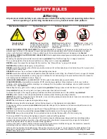
Page 6: ...is elevated STOP carefully lower platform Move machine to a firm level surface Climbing up the railing of the platform standing on or stepping from the platform onto buildings steel or prefab concrete...

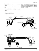
Page 7: ...NUMBERS from the equipment nameplate Should the nameplate be missing the SERIAL NUMBER is also stamped at the rear of the chassis Right Side Chassis Lower Controls Upper Controls Operator s Manual St...

Page 8: ...ff and back on resetting the system At that time the machine functions are operational Caution The emergency power system is for emergency low ering and stowing only The length of time the pump can be...

Page 9: ...re all personnel stand clear while operating the aerial platform Controls to position the platform are located on the lower control panel on the turntable and on the upper control panel in the platfor...

Page 10: ...e When the ambient temperature range is 10 C 50 F to 5 C 23 F press and hold the preheat button for five seconds before starting the engine When the ambient temperature is below 5 C 23 F press and hol...

Page 11: ...the upper control panel Note Machine functions are not operational while using the hydraulic warm up system To warm up the hydraulic fluid from the lower controls 1 Start the engine from the lower con...

Page 12: ...erate the aerial platform Push the emergency stop button inward when the upper controls are not in use to protect against unin tentional operation Drive Boom Selector Switch The drive boom selector sw...

Page 13: ...y low ering and stowing only The length of time the pump can be operated depends on the capacity of the bat tery Do not use this system for normal operation Hold the engine emergency power switch down...

Page 14: ...he proper level 4 Check that all guardrails are in place and all fasteners are properly tightened 5 Inspect the machine thoroughly for cracked welds and structural damage loose or missing hardware hyd...

Page 15: ...sing or loose parts 5 Test each machine function jib platform level plat form rotate elevation rotation extension from the lower control station by holding the ground operation switch up while operati...

Page 16: ...does not flow well and may cause delay in response to control movement Cold hydraulic oil may also cause cavitation and pump damage Hydraulic System Cold Weather Warm Up Some machines may have a hydra...

Page 17: ...perating the boom and turntable control toggle switches 6 Release the function toggle switch to stop move ment 7 Place the ground operation switch in the off position when no functions are being opera...

Page 18: ...t When the turntable is rotated from the stowed position with the booms to either side of or in front of the chassis the direction of control movement does not correspond with the direction of chassis...

Page 19: ...onnector on the right side of the chassis Unplug the source of power before moving the aerial platform AC Generator The optional generator supplies power to the electrical outlet only when the engine...

Page 20: ...s Key Switch to OFF and remove the key to prevent unauthorized operation Emergency Lowering Warning If the platform should fail to lower NEVER climb down the elevating assembly Stand clear of the elev...

Page 21: ...ock Caution Ratchets winches and come alongs can produce enough force to damage machine components Do not over tighten the straps or chains when securing the aerial platform to the transport vehicle 3...

Page 22: ...engine tray Oil Level Check the engine oil level before starting the engine so the oil has drained to the pan The proper oil level is between the add and full marks on the dipstick The distance betwe...

Page 23: ...at the specified intervals and after prolonged periods of storage before returning the machine to ser vice Inspection and maintenance shall be performed by personnel who are trained and familiar with...

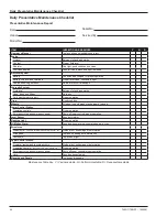
Page 24: ...er Control Station Operating controls Proper operation Emergency stop and emergency power Shuts off lower controls proper operation Level Sensor Sounds tilt alarm Flashing Light Proper operation All M...

Page 25: ...Decal Location LOW ER CONTROLS ENGINE DIPSTICK INSIDE ON CIRCUIT BREAKER PANEL ANSI ONLY CE ONLY ANSI ONLY CE ONLY T46JRT ONLY INSIDE ON HYDRAULIC RESERVOIR INSIDE ABOVE GREASE FITTING INSIDE ON DIESE...

Page 26: ...rief operating instructions swedish 0162328w 2 Decal additional operating instructions swedish ITEM PART NO QTY DESCRIPTION 0162329d 2 Decal brief operating instructions dutch 0162328d 2 Decal additio...

Page 27: ...10e 3 Decal DNGR ROTATING PARTS english 0151410f 3 Decal DNGR ROTATING PARTS french 0151410p 3 Decal DNGR ROTATING PARTS spanish 0151410w 3 Decal DNGR ROTATING PARTS swedish 0151410d 3 Decal DNGR ROTA...

Page 28: ...1 18 ft s Down 43 seconds minimum 0 36 m s 1 18 ft s Extend 32 to 35 seconds Retract 32 to 37 seconds Platform rotation 17 to 22 seconds Drive High booms stowed 6 8 km h 1 9 m s 4 25 mph Mid booms st...

Page 29: ...nimum Retract 29 seconds minimum Jib Up 20 seconds minimum Down 20 seconds minimum Platform rotation 17 to 22 seconds Drive High booms stowed 6 8 km h 1 9 m s 4 25 mph Mid booms stowed 3 2 km h 0 89 m...

Page 30: ...l Distributore locale EUROPE MIDDLE EAST AFRICA ASIA PHONE 44 0 845 1550 058 FAX 44 0 845 1557 756 NORTH SOUTH AMERICA PHONE 1 785 989 3000 TOLL FREE 1 800 255 0317 FAX 1 785 989 3070 AUSTRALIA PHONE...

Reviews: